Galaxy PG1 User Manual
Overview
E-Metrotel's Galaxy PG1 is a SIP to Paging and Video intercom device for use in various industry applications. The media stream transmission adopts standard IP/RTP/RTSP protocol, with the stability and sound quality of an IP phone. It has various functions and interfaces that include intercom, broadcast, video, security and recording. It can adapt to different application environments and is simple to install, making PG1 ideal for any business.

Table of Contents
1. Device Port Description
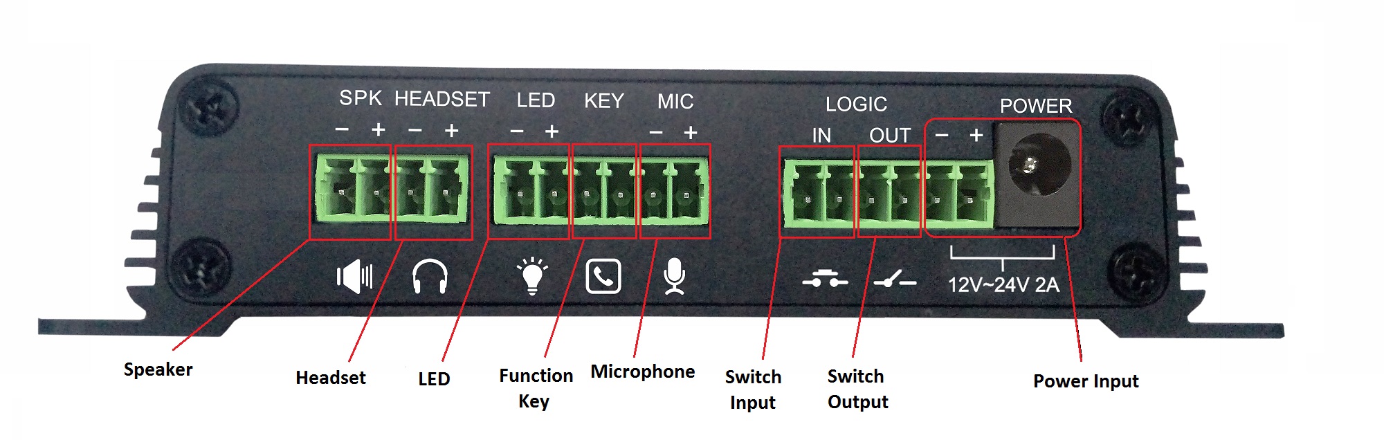
| Speaker | External Amplified Speaker ports. The input power adapter size needs to correspond to the output speaker wattage. Recommend using 18 AWG gauge speaker wire. |
|---|---|
| Headset | External panel speaker or headset ports. Signal output impedance 32Ω and voltage 1.2V. |
| LED | External LED ports for registration, network and call status. Output voltage 5V and current 5mA. |
| Function key | External Function key ports for connecting buttons or door bells etc. When engaged a phone number can be speed dialed. |
| Microphone |
External Microphone ports. Recommend using 2.2kΩ impedance electret condenser microphone, sensitivity -38dB, bias voltage 2.2V. Use a shielded cable and do not connect the cable to the grounding screw. |
| Switch input | Security sensor ports. Example: Door sensor, infrared probe or an emergency switch. |
| Switch output |
External ports for alarm lights, electric locks and other similar equipment. Use the adjacent ⑧ power port connection for external equipment power supply. |
| Power input |
12V ~ 24V 2A input. The maximum output power amplifier is determined by the input voltage. The device supports PoE. Power adapter is not included. |
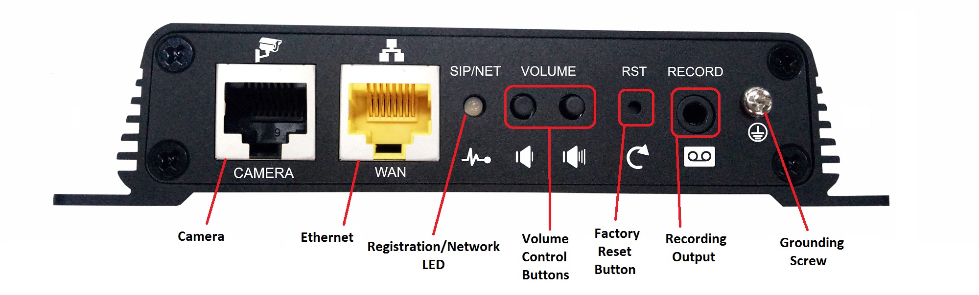
| Camera | Standard RJ45 interface for security camera. This port is reserved for future use. |
|---|---|
| Ethernet | 10M/100M ethernet WAN port. PoE supported |
| Registration / Network LED |
Indicates the network status, call status, registration status.
|
| Volume Control buttons |
Volume adjustments depending on state of the device:
Press and hold the volume down key to broadcast the IP address. |
| Factory reset button | Press and hold for 3 seconds to flash the device to restart and restore the factory settings. |
| Recording output | External ports for recording devices or computer mic input. |
| Grounding screw | Grounding screw for external devices to prevent static build and shock to system. |
2. Device Installation
Step One
Install device securely in desired location using the provided screw slots.
Step Two
Connect Speakers and other external equipment to the back of the unit as desired. It is recommended to attach a grounding cable.
Step Three
Plug the network cable into a PoE enabled switch, the device light flashes when the power connection is normal.
3. Discover IP address
There are 3 methods to find the IP address of the device.
Method One
Download the simple Network Scanner tool from iDoorPhone: https://idoorphonenetworkscanner.software.informer.com/1.0/
Run the Network Scanner tool. Press the Refresh button to search the door phone and find the IP address of the E-MetroTel Galaxy PG1 device.

Method Two
Make sure speakers are connected to the device first, then press the volume down button for 3 seconds, the device will automatically voice broadcast the device's IP address.
Method Three
Make sure speakers are connected to the device first, then press and hold the volume up button for 10 seconds, when a rapid beep is played, quickly press the volume up button 3 times and the beep will stop. Wait 10 seconds. The device will switch switch to Dynamic IP and voice broadcast its IP address.
Repeating the above steps will toggle the network mode back to Static IP address.
4. Basic Operation
Answer a Call
If auto answer feature (Enable Auto Answer) is enabled, an incoming call is answered automatically. If Auto Answer Timeout is set to greater than 0, the call will ring for the set time and then auto answered.
Configuration is done under the Intercom settings -> Features page.
Make a Call
Configure function key as a Hot key with the desired target number(s). To make a call, press the function key and a call will be made to the configured number(s).
Configuration is done under the Function Key page.
End Call
The function key can be configured to end a call when pressed. On the Function Key page, use one of the following two methods:
-
Configure DSS key as Key Event, subtype Release
OR - Configure DSS key as Hot Key and set Use Hot Key to Hangup to Enable
Security linkage
If the switch input port connected to a door, emergency button or other sensory device receives a signal, the output port connected to alarm lights, electric locks or other equipment will automatically respond and send the alarm information.
Input, Output and Trigger settings are configured under the Security settings page.
Video linkage
Connect camera to the switch input port. For camera configuration, please refer to the section on Camera settings.
5. Web Configuration
Accessing the Web Interface
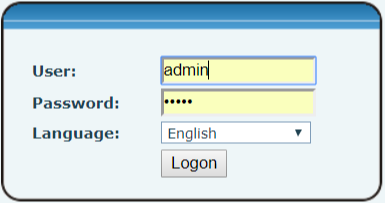
Enter the IP address of the PG1 device from a browser window. The default IP address of the device is 192.168.1.128.
Login using the default administrator login credentials:
- Username = admin
- Password = admin
5.1 System
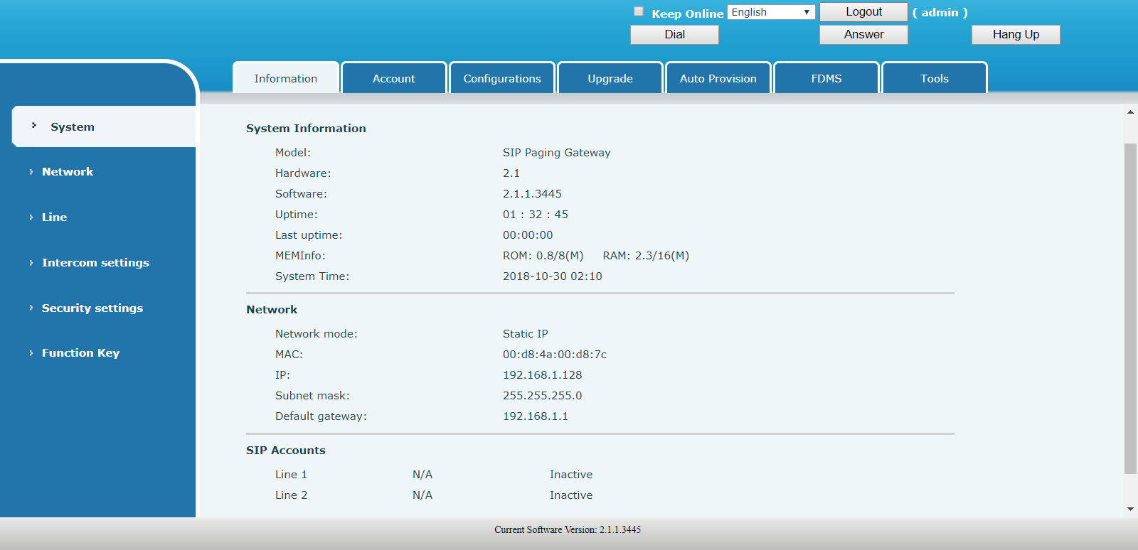
System - Information
| FIELD | DESCRIPTION |
|---|---|
| System Information | Display equipment model, hardware version, software version, uptime, last uptime, MEMInfo and system time. |
| Network | Shows the configuration information of WAN port, including connection mode of WAN port (Static, DHCP, PPPoE), MAC address, IP address of WAN port. |
| SIP Accounts | Shows the phone numbers and registration status of the 2 SIP LINES. |
System - Account
There are two types of user accounts: Administrators and Users.
- Users: Can set all configuration parameters except server parameters for SIP
- Administrators: Can set all configuration parameters
A default adminstrator user account is provided:
- Username: admin
- Password: admin

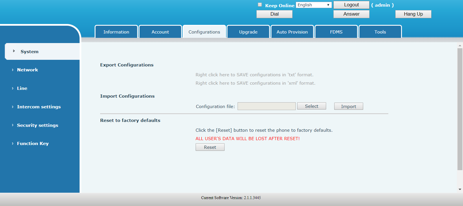
System - Configurations
| FIELD | DESCRIPTION |
|---|---|
| Export Configurations | Save the equipment configuration to a TXT or XML file. Right click on the desired file type and select Save link as ... |
| Import Configurations | Click Select and find the saved configuration file. Then click Import to load the configuration. |
| Reset to factory defaults | Device will be restored to factory default configuration. All existing configuration will be erased. |
System - Upgrade
Click Select and find the software image file, then click Upgrade to load the new software version.

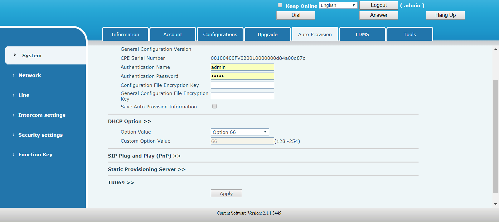
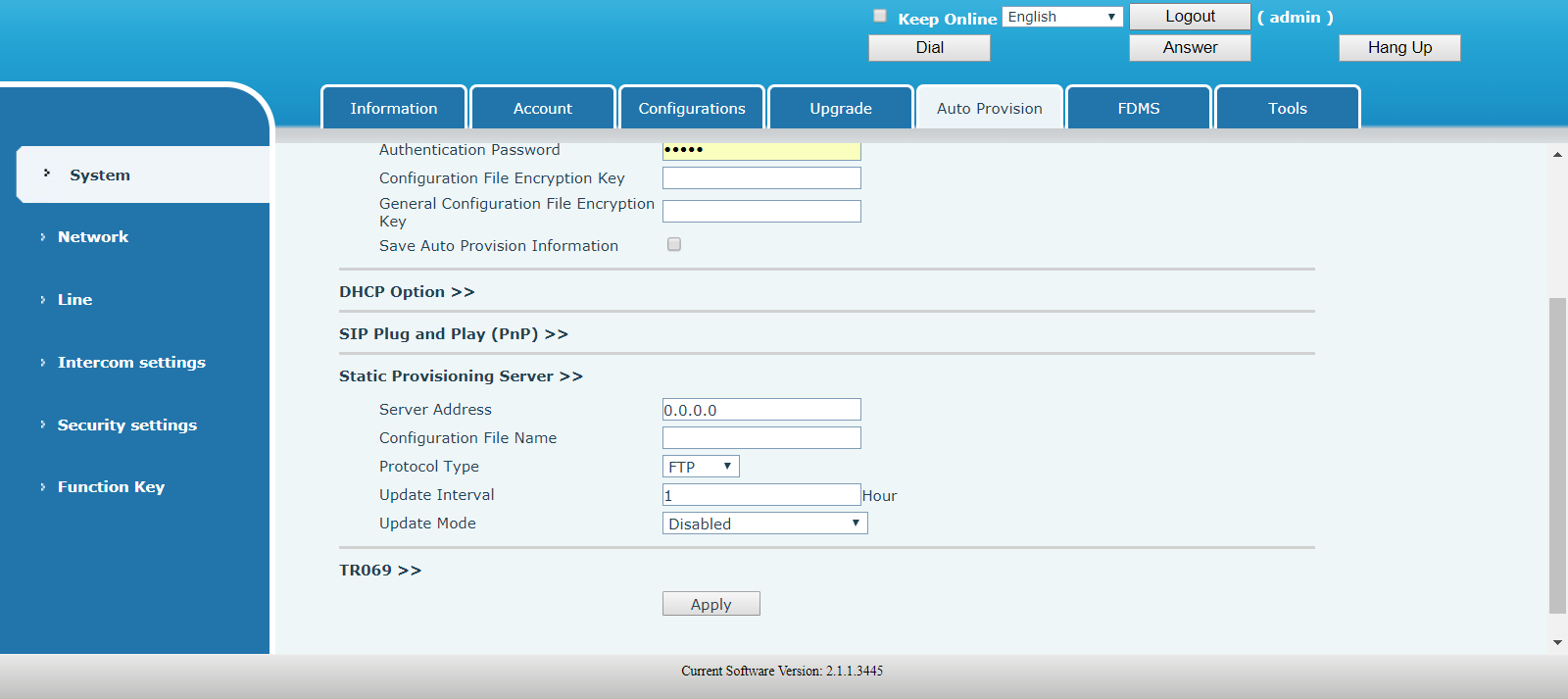
System - Auto Provision
Common Settings
| FIELD | DESCRIPTION |
|---|---|
| Current Configuration Version |
Shows the current config file version. If the config file to be downloaded is higher than the current version, the configuration would be upgraded. If the endpoints confirm the configuration by the Digest method, the configuration would not be upgraded unless it differs from the current configuration. |
| General Configuration Version |
Shows the common config file version. If the config file to be downloaded and this version is the same, the auto provision would stop. If the endpoints confirm the configuration by the Digest method, the configuration would not be upgraded unless it differs from the current configuration. |
| CPE Serial Number | Serial number of the equipment. |
| Authentication Name | Username for the FTP/HTTP/HTTPS configuration server. If this field is blank, anonymous will be used. |
| Authentication Password | Password for the FTP/HTTP/HTTPS configuration server. |
| Configuration File Encryption Key | Encryption key for the configuration file. |
|
General Configuration File Encryption Key |
Encryption key for common configuration file. |
|
Save Auto Provision Information |
Save the auto provision username and password in the phone until the server URL changes. |
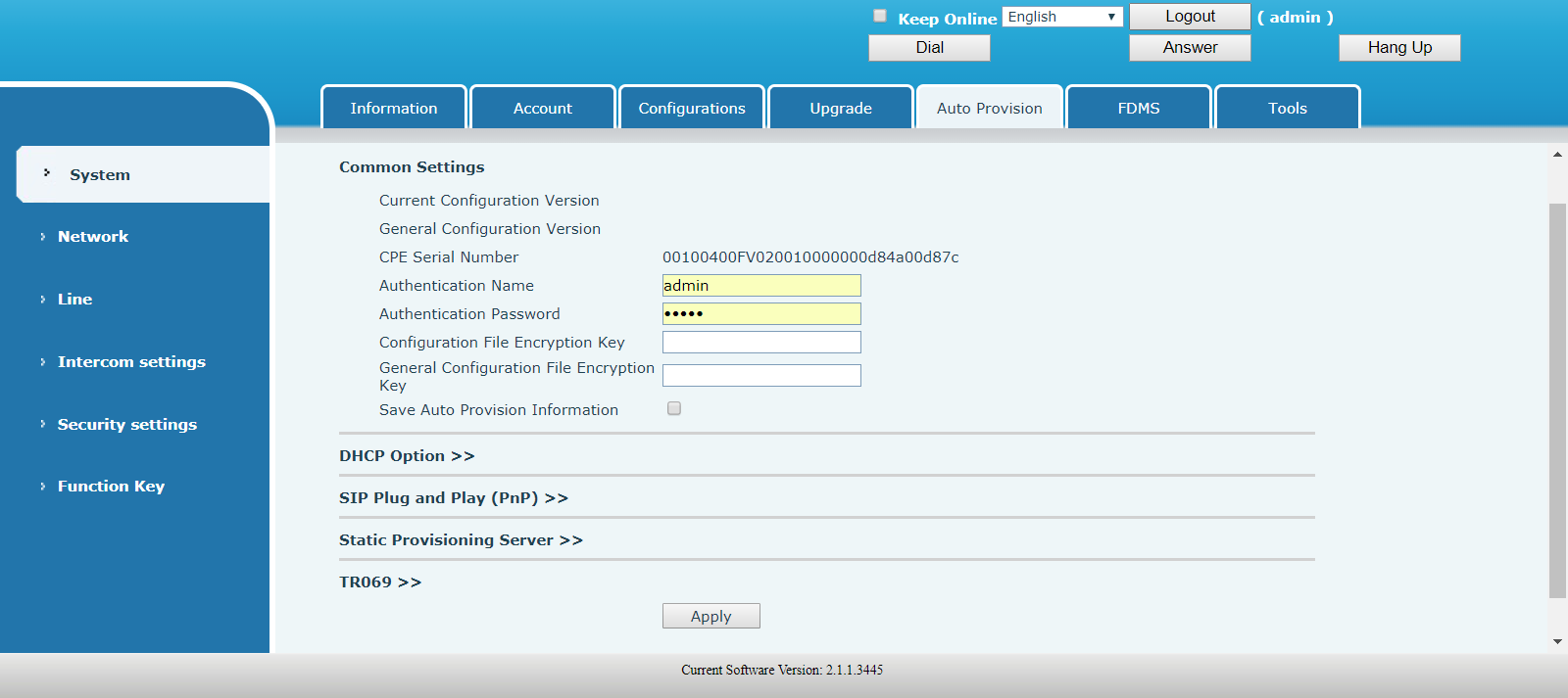
DHCP Option
| FIELD | DESCRIPTION |
|---|---|
| Option Value | The device supports Option 43, Option 66, Custom Option or it can be Disabled. |
| Custom Option Value | This field is enabled only when Custom Option is selected. The DHCP option value must be from 128 to 254. |
SIP Plug and Play
| FIELD | DESCRIPTION |
|---|---|
| Enable SIP PnP | If it is enabled, the device sends SIP SUBSCRIBE messages to the server address when it boots up. Any SIP server compatible with that message will reply with a SIP NOTIFY message containing the Auto Provisioning Server URL where the phones can request their configuration. |
| Server Address | PnP Server Address |
| Server Port | PnP Server Port |
| Transportation Protocol | PnP Transfer protocol – UDP or TCP |
| Update Interval | Interval time for querying PnP server. Default is 1 hour. |

Static Provisioning Server
| FIELD | DESCRIPTION |
|---|---|
| Server Address | Set FTP/TFTP/HTTP server IP address for auto update. The address can be an IP address or domain name with subdirectory. |
| Configuration File Name | Specify configuration file name. The device uses its MAC ID as the config file name if this is left blank. |
| Protocol Type | Specify the protocol type FTP, TFTP or HTTP. |
| Update Interval | Specify the update interval time. Default is 1 hour. |
| Update Mode |
Disable – Not to update Update After Reboot – Update only after reboot. Update at Time Interval – Update at every update interval. |
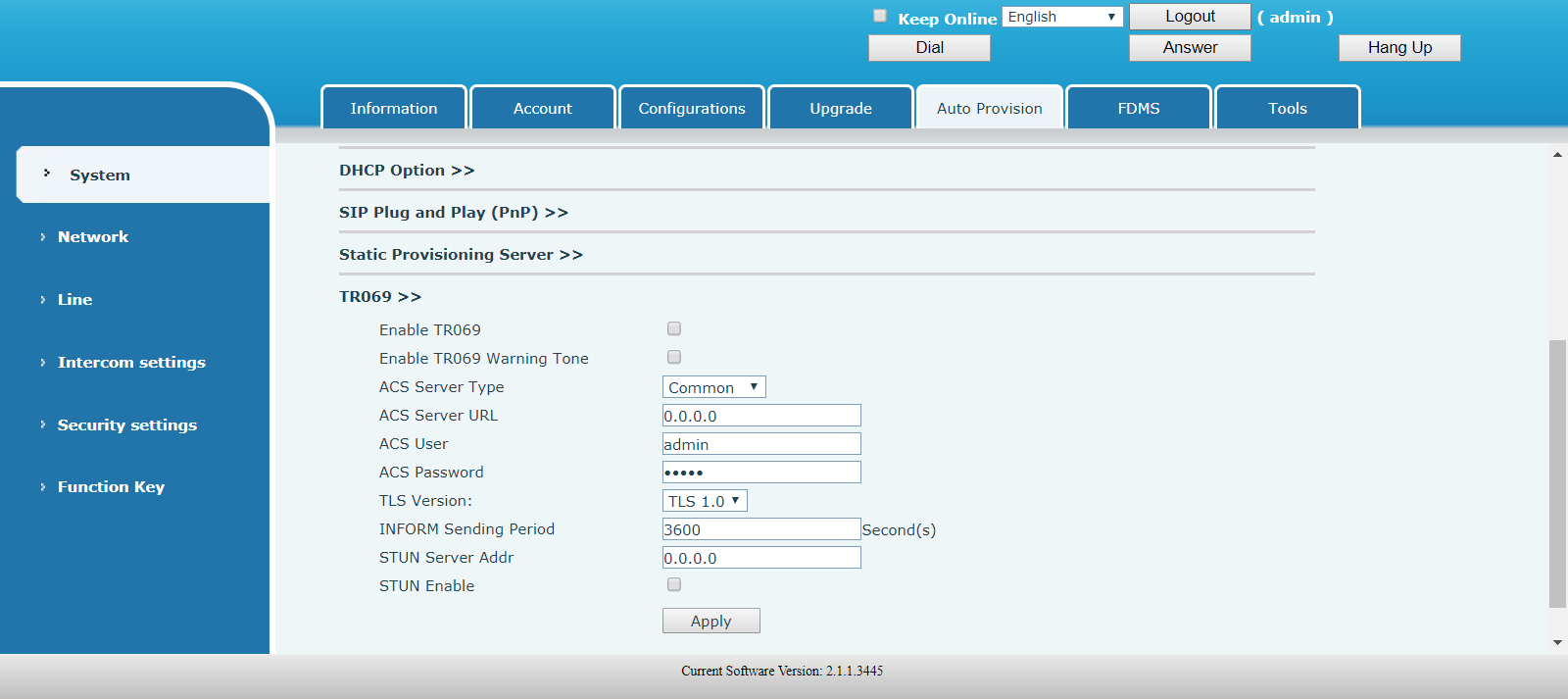
TR069
| FIELD | DESCRIPTION |
|---|---|
| Enable TR069 | Enable/Disable TR069 configuration. |
| Enable TR069 Warning Tone | Enable/Disable TR069 warning tone. |
| ACS Server Type | Select the server type from the drop-down list. |
| ACS Server URL | ACS Server URL. |
| ACS User | Username of ACS. |
| ACS Password | ACS password. |
| TLS Version | Select the TLS version from the drop-down list. |
| INFORM Sending Period | Time between transmissions of INFORM. The value is in seconds. |
| STUN Server Addr | Enter the STUN server address. |
| STUN Enable | Enable/Disable STUN. |
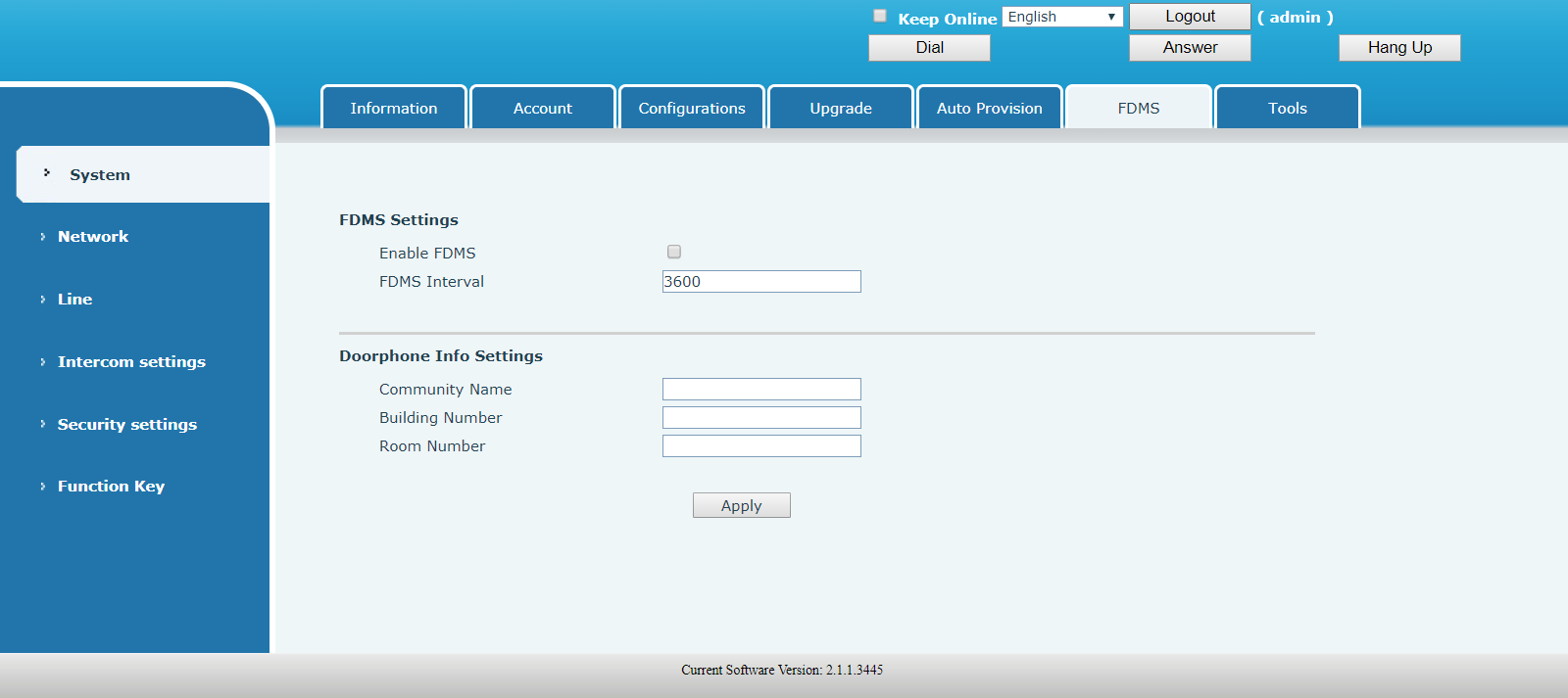
System - FDMS
FDMS Settings
| FIELD | DESCRIPTION |
|---|---|
| Enable FDMS | Display equipment model, hardware version, software version, uptime, last uptime, MEMInfo and system time. |
| FDMS Interval | Shows the configuration information of WAN port, including connection mode of WAN port (Static, DHCP, PPPoE), MAC address, IP address of WAN port. |
Doorphone Info Settings
| FIELD | DESCRIPTION |
|---|---|
| Community Name | The name of the community where the device is installed. |
| Building Number | The name of the building where the device is installed. |
| Room Number | The name of the room where the device is installed. |
System - Tools
Syslog
Syslog is a protocol used to record log messages using a client/server mechanism. The Syslog server receives the messages from clients, and classifies them based on priority and type. Then these messages would be written into a log by rules which the administrator has configured. There are 8 levels of syslog information.
- Emergency: System is unusable. This is the highest debug info level.
- Alert: Action must be taken immediately.
- Critical: System is probably working incorrectly.
- Error: System may not work correctly.
- Warning: System may work correctly but needs attention.
- Notice: It is normal but significant condition.
- Information: It is normal daily messages.
- Debug: Debug messages normally used by system designer. This level can only be displayed via telnet.
Network Packets Capture
Capture packet streams from the device. This is normally used to troubleshoot problems.
Auto Reboot Setting
Reserved for future use.
Reboot Phone
Some configuration changes require a reboot to take effect. Click the Reboot button to reboot immediately.
Note: Be sure to save the configuration before rebooting.

5.2 Network
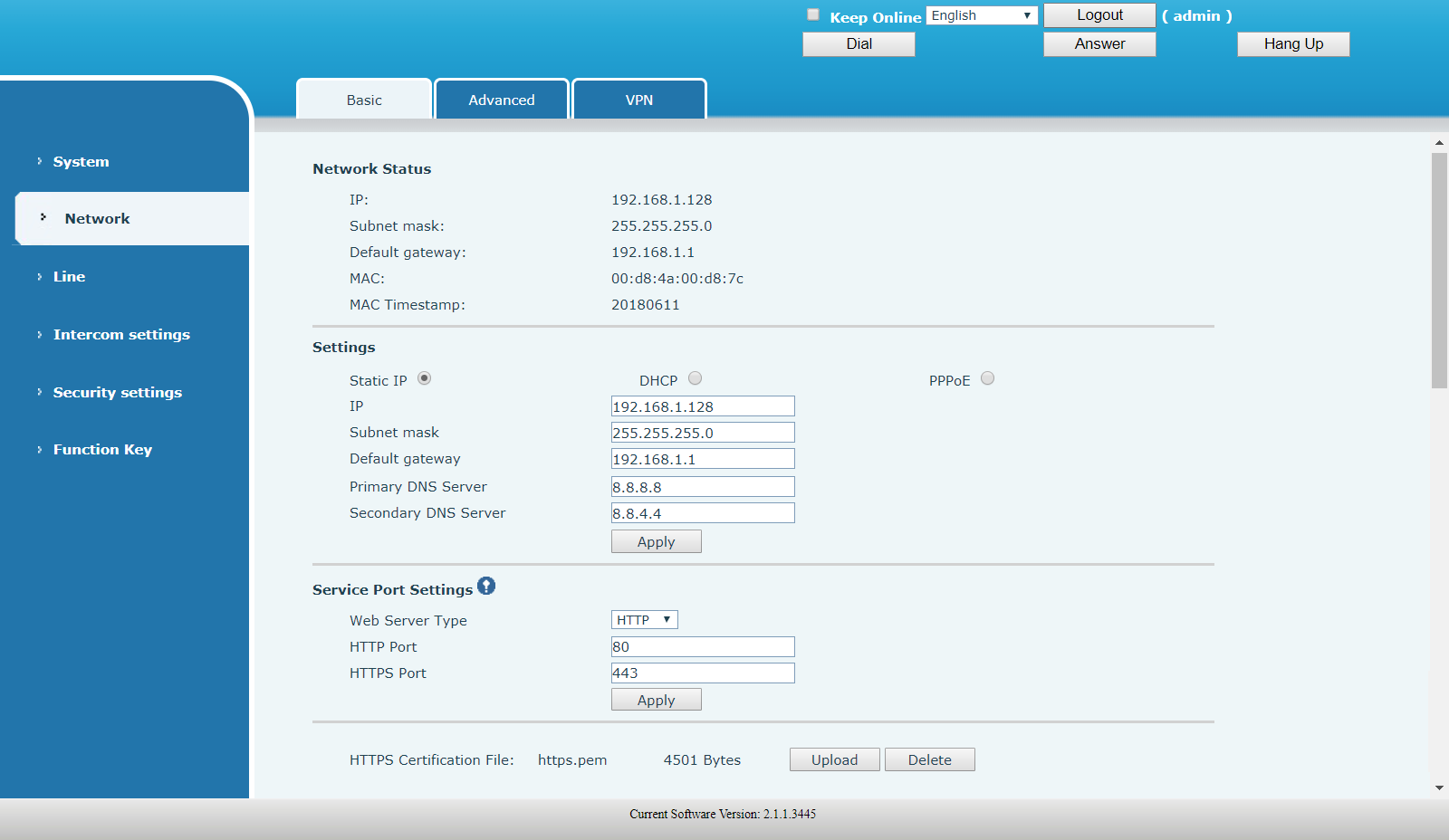
Network - Basic
Network Status
Displays the network information of the device.
Settings
Select the network mode: Static IP or DHCP or PPPoE.
The fields below will change based on the mode selected.
Click the Apply button to save the new settings. If the IP address of the device has been changed, you have to relogin to the web interface with the new IP address.
| FIELD | DESCRIPTION |
|---|---|
| Static IP | Network parameters must be entered manually and does not change. |
| DHCP | Network parameters are provided automatically by a DHCP server. |
| PPPoE | Account and Password must be input manually. These are provided by your ISP. |
Service Port Settings
If modifying the HTTP(S) ports, the new port must be greater than 1024.
Click the Apply button to save the new settings and reboot the device.
HTTPS Certification File
Upload or Delete the certification file.
Network - Advanced

Network - VPN
The device supports remote connection via VPN. It supports both Layer 2 Tunneling Protocol (L2TP) and OpenVPN protocol. (Only one protocol can be activated.)
This allows users at remote locations on the public network to make secure connections to local networks.
Once the selection and configuration is saved, the phone must be rebooted.
| FIELD | DESCRIPTION |
|---|---|
| VPN IP Address | Shows the current VPN IP address. |
| VPN Mode | |
| Enable VPN | Enable/Disable VPN. |
| L2TP | Select Layer 2 Tunneling protocol. |
| OpenVPN | Select OpenVPN prootocol. |
Layer 2 Tunneling Protocol (L2TP)
If L2TP mode is selected, then fill in the parameters under this section.
OpenVPN Files
If OpenVPN mode is selected, then Upload or Delete the OpenVPN cerfification files here.

5.3 Line
Line - SIP
| FIELD | DESCRIPTION |
|---|---|
| Line | Choose the SIP line to configure |
| Line Status | Displays the current line status. To update the line status, refresh the page manually. |
| Phone number | The extension number of the account. |
| Display name | The display name of the account. |
| Authentication Name | The username of the account. |
| Authentication Password | The password or secret of the account. |
| Activate | Active/Deactivate the line. |
| SIP Proxy Server Address | Enter the IP address or FQDN of the SIP server address. |
| SIP Proxy Server Port | Enter the SIP server port number. Default is 5060. |
| Backup Proxy Server Address | Enter the IP address or FQDN of the Backup SIP server address. |
| Backup Proxy Server Port | Enter the Backup SIP server port number. Default is 5060. |
| Outbound proxy address | Enter the IP or FQDN address of outbound proxy server. |
| Outbound proxy port | Enter the outbound proxy server port. |
| Realm | Enter the SIP domain if requested by the service provider. |
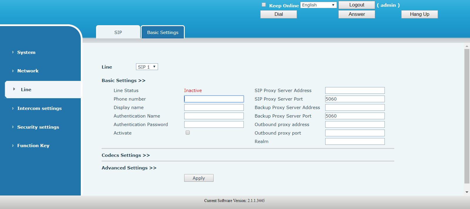
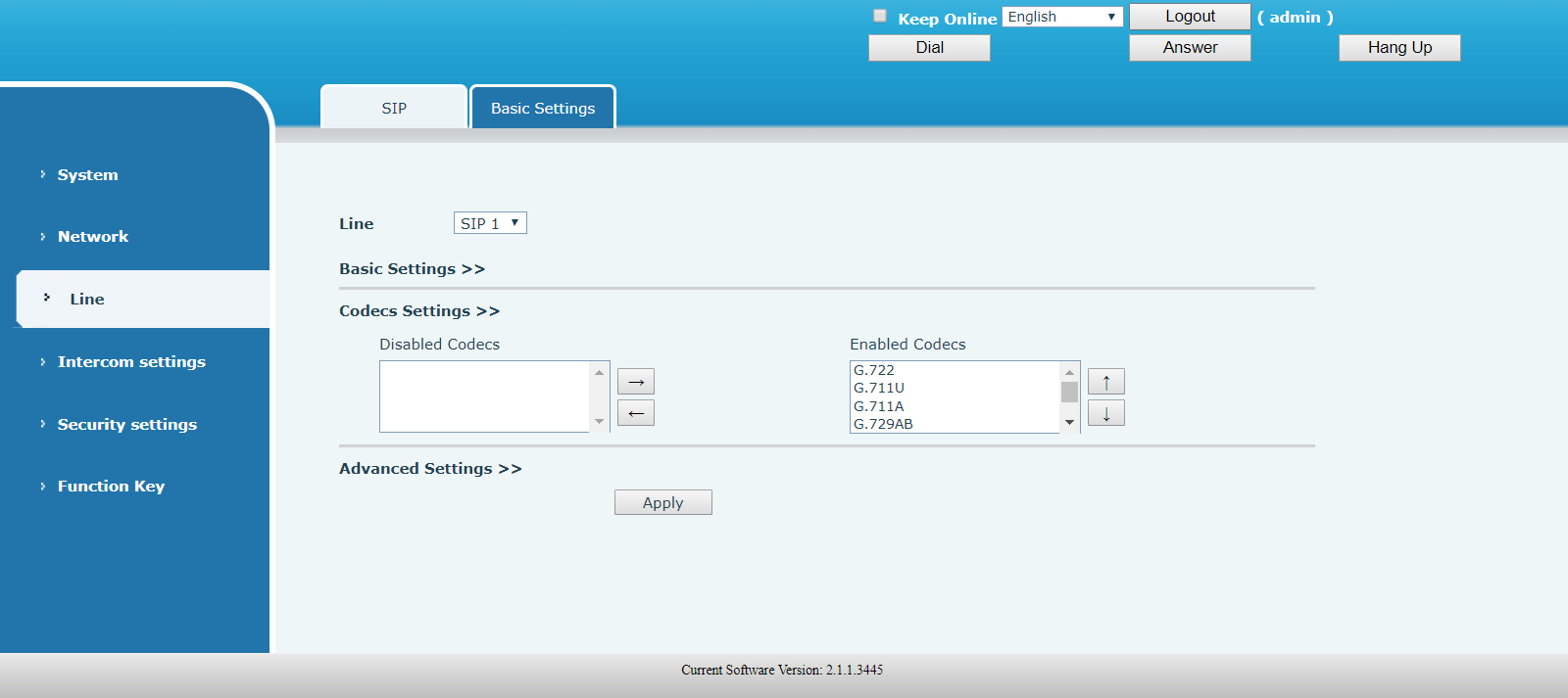
Codecs Settings
Set the priority and availability of the codecs by adding or remove them from the list.
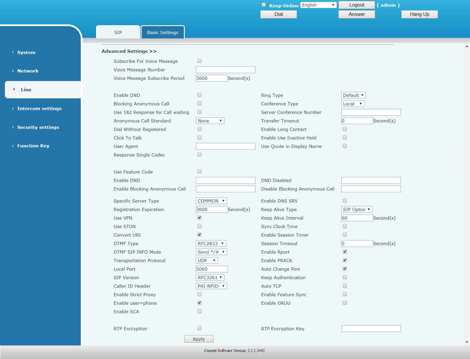
Advanced Settings
| FIELD | DESCRIPTION |
|---|---|
| Subscribe for Voice Message | Enable the device to subscribe for voice message waiting notification. If enabled, the device will receive notification from the server if there is voice message waiting on the server. |
| Voice Message Number | Set the number for retrieving voice message. |
|
Voice Message Subscribe Period |
Set the interval of voice message notification subscription. |
| Enable DND | Enable Do-not-disturb, any incoming call to this line will be rejected automatically. |
| Blocking Anonymous Call | Reject any incoming call that does not have a CallerID. |
| Use 182 Response for Call waiting | Set the device to use 182 response code for call waiting. |
| Anonymous Call Standard | Select from the drop-down list the standard to be used for anonymous calls. |
| Dial Without Registered | Allow call out by proxy without registration. |
| Click To Talk | Allow Click to Talk. |
| User Agent | Set the user agent, the default is Model with Software Version. |
| Response Single Codec | If enabled, the device will use single codec in response to an incoming call request. |
| Ring Type | Select the ring tone type from the drop-down list. |
| Conference Type |
Seelct from the drop-down list the type of call conference.
|
| Server Conference Number | Conference number to dial when conference type is set to be Server. |
| Transfer Timeout | Set the timeout value (in seconds) for call transfers. |
| Enable Long Contact | Allow more parameters in contact field per RFC 3840. |
| Enable User Inactive Hold | |
| Use Quote in Display Name | Add quote in display name. |
| Use Feature Code | When this setting is enabled, the features in this section will be controlled by the server instead of the device. Feature control is done by dialing the number specified in each feature code field. |
| Enable DND | Number to dial to enable DND. |
| Enable Blocking Anonymous Call | Number to dial to enable blocking anonymous call. |
| DND Disabled | Number to dial to disable DND. |
| Disable Blocking Anonymous Call | Number to dial to disable blocking anonymous call. |
| Specific Server Type | Set the line to collaborate with specific server type. Use COMMON for UCx Server. |
| Registration Expiration | Set the SIP expiration interval. |
| Use VPN | Set the line to use VPN restrict route. |
| Use STUN | Set the line to use STUN for NAT traversal. |
| Convert URI | Convert non digits and alphabetic characters to $hh hex code. |
| DTMF Type |
Select from the drop-down list the DTMF type to be used for the line:
|
| DTMF SIP INFO Mode |
Select from the drop-down list the SIP INFO mode:
|
| Transportation Protocol |
Select protocol to use for SIP transmission from the drop-down list:
|
| Local Port | Set the local port. Default is 5060. |
| SIP Version |
Select the SIP version:
|
| Caller ID Header |
Select the Caller ID header:
|
| Enable Strict Proxy | Enables the use of strict routing. When the phone receives packets from the server, it will use the source IP address, not the address in via field. |
| Enable user=phone | Sets user=phone in SIP messages. |
| Enable SCA | Enable/Disable SCA (Shared Call Appearance ) |
| Enable DNS SRV | Set the line to use DNS SRV which will resolve the FQDN in proxy server into a service list. |
| Keep Alive Type |
Select the NAT keep alive type:
|
| Keep Alive Interval | Set the keep alive packet transmitting interval. |
| Sync Clock Time | |
| Enable Session Timer | Set the line to enable call ending by session timer refreshment. The call session will be ended if there is not new session timer event update received after the timeout period. |
| Session Timeout | Set the session timer timeout period. |
| Enable Rport | Set the line to add rport in SIP headers. |
| Enable PRACK | Set the line to support PRACK SIP message. |
| Auto Change Port | Enable/Disable Auto Change Port. |
| Keep Authentication | Keep the authentication parameters from previous authentication. |
| Auto TCP | Using TCP protocol to guarantee usability of transport for SIP messages above 1500 bytes. |
| Enable Feature Sync | Feature synchronization with server. |
| Enable GRUU | Support Globally Routable User-Agent URI (GRUU). |
| RTP Encryption | Enable RTP encryption such that RTP transmission will be encrypted. |
| RTP Encryption Key | Set the pass phrase for RTP encryption. |
Line - Basic Settings
SIP settings
| FIELD | DESCRIPTION |
|---|---|
| Local SIP Port | Set the local SIP port used to send/receive SIP messages. |
| Registration Faiure Retry Interval | Set the retry interval of SIP REGISTRATION when registration failed. |
| Enable Strickt UA Match | Enable or disable Strict UA Match. |
| Strict Branch |
STUN settings
A STUN (Simple Traversal of UDP through NAT) server allows a phone in a private network to know its public IP and port as well as the type of NAT being used. The device can then use this information to register itself to a SIP server so that it can make and receive calls while in a private network.
| FIELD | DESCRIPTION |
|---|---|
| STUN NAT Traversal | Shows status of STUN NAT Traversal. |
| Server Address | STUN Server IP address. |
| Server Port | STUN Server Port – Default is 3478. |
| Binding Period | STUN blinding period – STUN packets are sent at this interval to keep the NAT mapping active. |
| SIP Waiting Time | Waiting time for SIP. This will vary depending on the network. |
TLS Certification File
Upload or Delete the TLS certification file used for encrypted SIP transmission.

5.4 Intercom settings
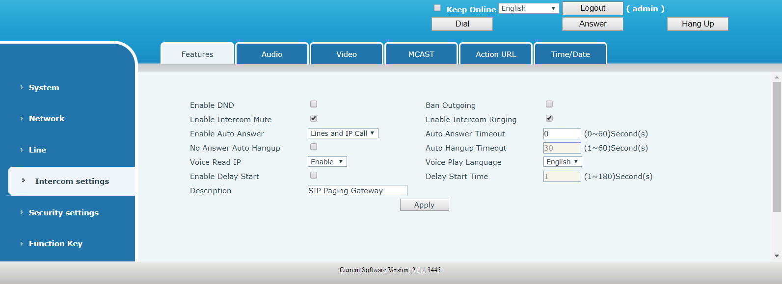
Intercom settings - Features
| FIELD | DESCRIPTION |
|---|---|
| Enable DND | If enabled, all incoming calls are rejected. Outgoing calls are not affected. |
| Enable Intercom Mute | If enabled, incoming calls are muted during an intercom call. |
| Enable Auto Answer | If enabled, incoming calls are automatically answered. |
| No Answer Auto Hangup | If enabled, hang up automatically when there is no answer. |
| Voice Read IP | Enable or disable voice broadcast IP address. |
| Enable Delay Start | Enable / disable start delay. |
| Description | Description displayed on IP scanning tool software or FDMS. |
| Ban Outgoing | If enabled, outgoing calls are disallowed. |
| Enable Intercom Ringing | If enabled, intercom ring tone will be played when there is a new incoming call. |
| Auto Answer Timeout | Set auto answer timeout. Call is auto answered after the set time. |
| Auto Hangup Timeout | Automatically hang up when there is no answer within the set time. |
| Voice Play Language | Set language of the voice prompt. |
| Delay Start Time | Se start delay time. |
Intercom settings - Audio
| FIELD | DESCRIPTION |
|---|---|
| First Codec | The first codec choice: G.711A/U, G.722, G.723.1, G.726-32, G.729AB |
| Second Codec | The second codec choice: G.711A/U, G.722, G.723.1, G.726-32, G.729AB, None |
| Third Codec | The third codec choice: G.711A/U, G.722, G.723.1, G.726-32, G.729AB, None |
| Fourth Codec | The fourth codec choice: G.711A/U, G.722, G.723.1, G.726-32, G.729AB, None |
| Fifth Codec | The fifth codec choice: G.711A/U, G.722, G.723.1, G.726-32, G.729AB, None |
| Sixth Codec | The sixth codec choice: G.711A/U, G.722, G.723.1, G.726-32, G.729AB, None |
| DTMF Payload Type | The RTP Payload type that indicates DTMF. Default is 101. |
| Default Ring Type | Select ring type from the drop-down list. |
| G.729AB Payload Length | G.729AB Payload length – adjust from 10 msec to 60 msec. |
| Tone Standard | Select the country tone standard from the drop-down list. |
| G.722 Timestamps | Select from: 160/20 ms or 320/20ms. |
| G.723.1 Bit Rate | Select from: 5.3kb/s or 6.3kb/s. |
| Speakerphone Volume | Set speaker volume level. |
| MIC Input Volume | Set MIC input volume level. |
| Broadcast Output Volume | Set broadcast output volume level. |
| Signal Tone Volume | Set audio signal output volume level. |
| Enable VAD | Enable or disable Voice Activity Detection (VAD). If VAD is enabled, G729 Payload length cannot be greater than 20 msec. |
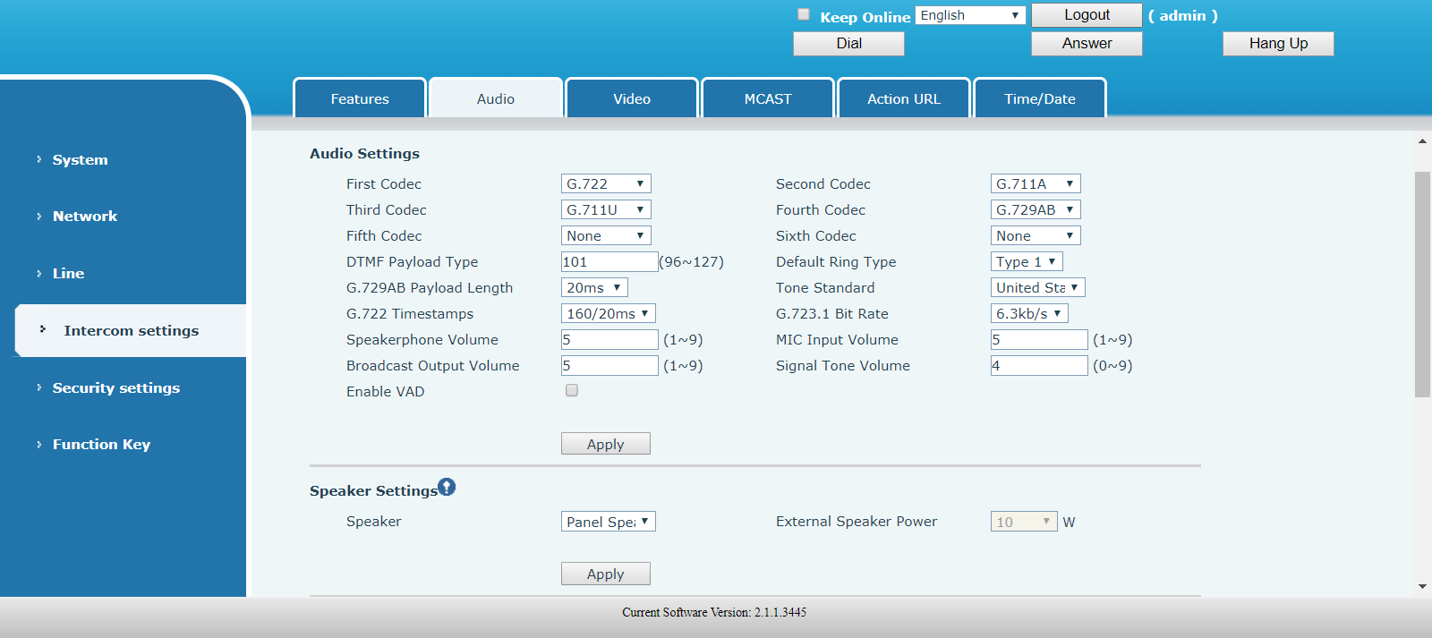
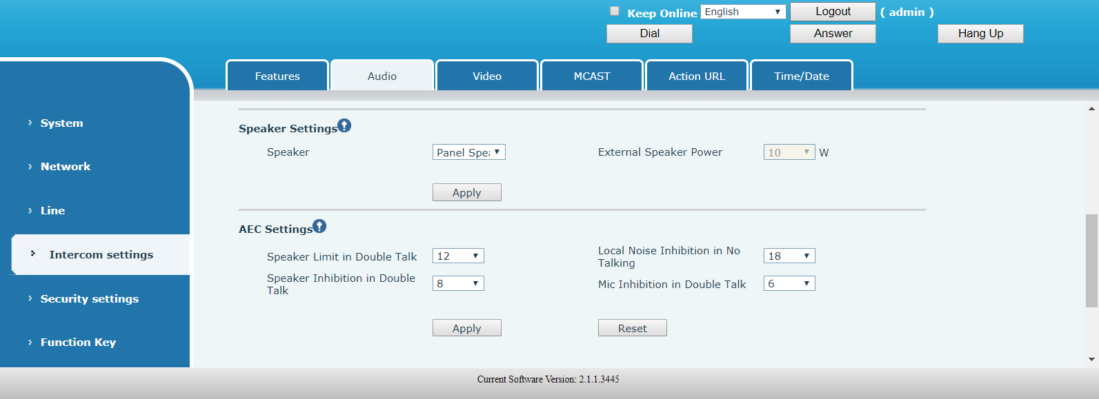
Speaker Settings
The Speaker Settings default mode is Panel Speaker. Use this mode when connecting to a device that contains both speakers and microphone. Device cabling is connected to the Headset ports. The output power is limited to 10W.
If external loud speakers are used for broadcasting, it can be changed to External Speaker mode. Device cabling is connected to the Speaker ports.
Select the speaker audio output wattage: 10W / 20W / 30W, and they must match the corresponding power supply as indicated in the table below:
| Input Power | Audio output | Speaker Type |
|---|---|---|
| POE | 10W | 10W/4Ω |
| 12V/2A DC | 10W | 10W/4Ω |
| 18V/2A DC | 20W | 20W/4Ω |
| 24V/2A DC | 30W | 30W/4Ω |
AEC Settings
Intercom settings - Video

IP Camera Settings
A security camera can either be connected directly to the unit or to the local network. It is recommended to use an external camera connected to the local network.
Perform the following steps to configure the device:
- For Connect mode, select External and click Apply
-
Under IP Camera Settings, configure the following parameters:
- User - External camera login account username
- Password - External camera login account password
- IP Camera brand - Select the camera's manufacturer
- IP - IP address of the camera
- Click the Apply button
PG1 will automatically connect to the external camera and display the status.

Intercom settings - MCAST
It is easy and convenient to use multicast function to send notice to each member of the multicast via setting the multicast key on the device and sending multicast RTP stream to pre-configured multicast address. By configuring monitoring multicast address on the device, the device monitors and plays the RTP stream which sent by the multicast address.
MCAST Settings
Equipment can be set up to monitor up to 10 different multicast addresses, used to receive the multicast RTP stream sent by the multicast address.
Here are the ways to change equipment receiving multicast RTP stream processing mode in the web interface:
Priority
In the drop-down box to choose priority of ordinary calls, if the priority of the incoming streams of multicast RTP, lower precedence than the current common calls, device would automatically ignore the group RTP streams. If the priority of the incoming stream of multicast RTP is higher than the current common calls priority, device would automatically receive the group RTP streams, and keep the current common calls in maintained status. You can also choose to disable the function in the receiving threshold drop-down box, the device would automatically ignore all local network multicast RTP streams. The options are as follows:
- 1 - 10 : To definite the priority of the common calls, 1 is the highest while 10 is the lowest
- Disable : ignore all incoming multicast RTP streams
Enable the page priority
Page priority determines the device how to deal with the new receiving multicast RTP streams when it is in multicast session currently. When Page priority switch is enabled, the device would automatically ignore the low priority multicast RTP streams but receive top-level priority multicast RTP streams, and keep the current multicast session in maintained statu; If it is not enabled, the device would automatically ignore all receiving multicast RTP streams.
Note: when you press the multicast key for multicast session, both multicast sender and receiver would beep.
Index/Priority
Multicast is a sign of listening, but also the monitoring multicast priority. The smaller number refers to higher priority.
Name
Define your monitoring multicast name.The group name would be displayed on the screen when you answer the multicast. If you have not set, the screen would display the Host:port value.
Host:port
It is a set of addresses and ports to listen, separated by a colon.

Multicast service
- Send: when you configure the item, pressing the corresponding key on the equipment shell, equipment would directly enter the Talking interface; the premise is to ensure no current multicast call and three-way conference, so the multicast can be established.
- Monitor: IP port and priority are configured to monitor the device, when the call is initiated by multicast and the call is successful; the device would directly enter the Talking interface.
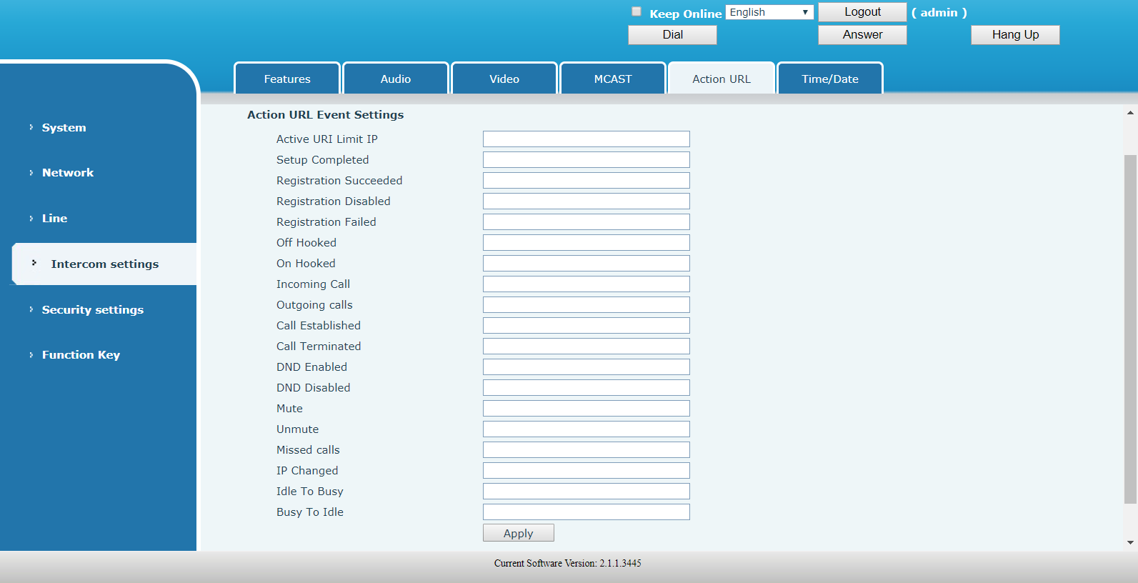
Intercom settings - Action URL
URL for various actions performed by the phone. These actions are recorded and sent as xml files to the server. Sample format is http://InternalServer/FileName.xml.
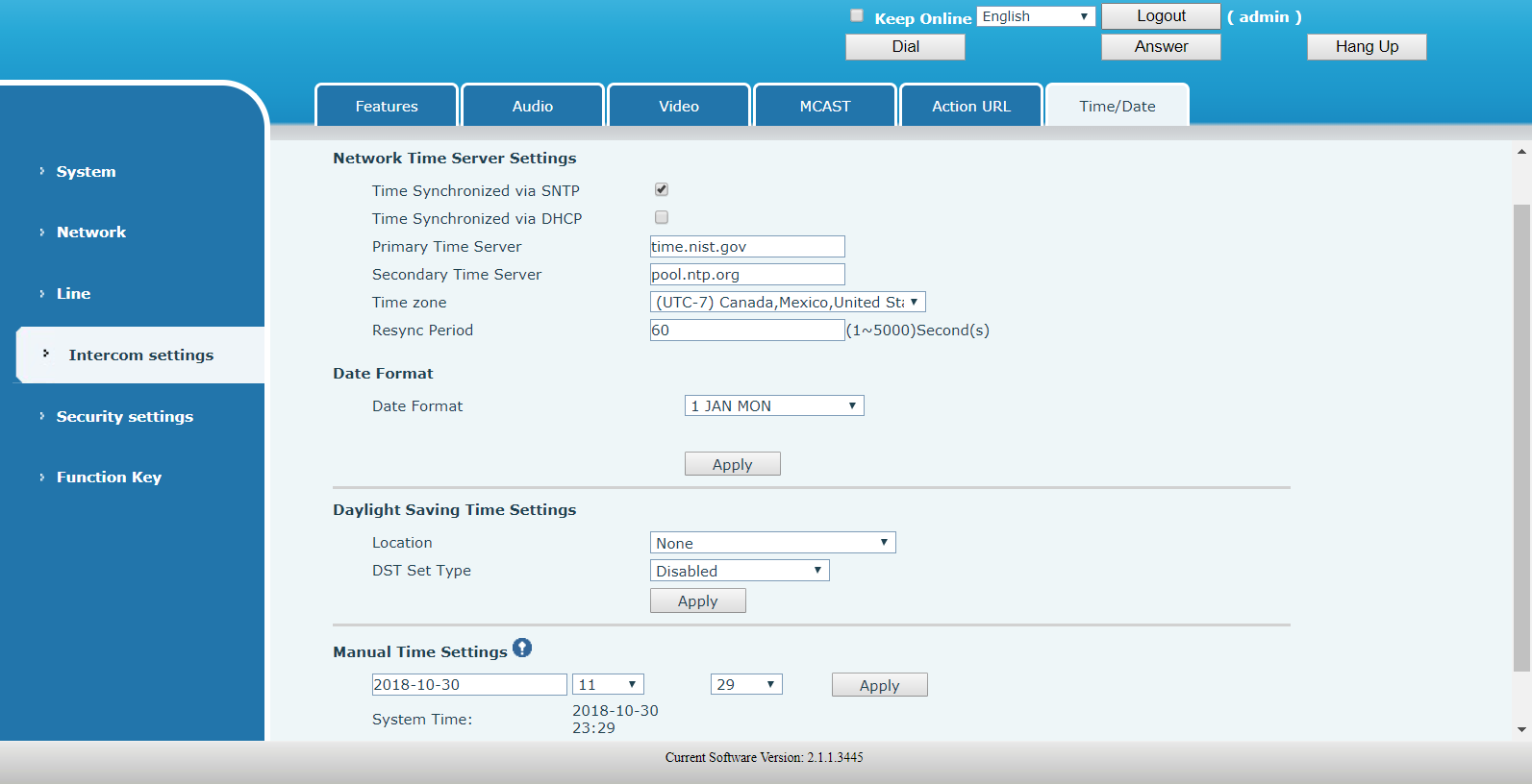
Intercom settings - Time/Date
Network Time Server Settings
Click on Apply to save the changes before proceeding to the next section.
| FIELD | DESCRIPTION |
|---|---|
| Time Synchronized via SNTP | Use SNTP protocol for time synchronization. |
| Time Synchronized via DHCP | Use DHCP protocol for time synchronization. |
| Primary Time Server | Set address of primary time server. |
| Secondary Time Server | Set address of secondary time server. |
| Time zone | Select time zone from the drop-down list. |
| Resync Period | Time interval for resynchronization wiht time server. |
| Date Format | Select format from the drop-down list. |
| Date Separator |
This field is displayed only when certain date formats are selected. Choose the separator used for the date:
|
Daylight Saving Time Settings
Click on Apply to save the changes.
| FIELD | DESCRIPTION |
|---|---|
| Location |
Select location from the drop-down list. Note: the list of locations available in the drop-down list will change based on your time zone setting. |
| DST Set Type |
Select from: Disabled, Automatic, Manual If Manual is selected, more fields will be displayed where you can define the rules for DST start and end. |
Manual Time Settings
Set the time manually here. Note that SNTP must be disabled first.
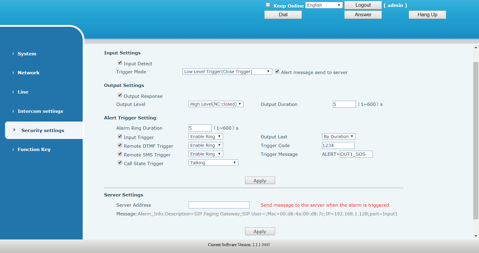
5.5 Security settings
| FIELD | DESCRIPTION |
|---|---|
| Input Settings | |
| Input Detect | Enable / disable input detect. |
| Trigger Mode |
Low Level Trigger (Closed Trigger) - detect the input port (low level) closed trigger. High Level Trigger (Disconnected Trigger) - detect the input port (high level) disconnected trigger. |
| Alert message send to server | Enable or disable Input port send message to server |
| Output Settings | |
| Output Response | Enable / disable output response |
| Output Level |
Low Level (NO: open) - when trigger condition is met, trigger the NO port disconnected. High Level (NO: closed) - when trigger condition is met, trigger the NO port close. |
| Output Duration | The port changes the duration. Default value is 5 seconds. |
| Alert Trigger Setting | |
| Alarm Ring Duration | Duration of alarm ring |
| Input trigger |
When the input port trigger condition is met, the output port will trigger (The Port level time change, By < Output Duration > control). You can choose to enable or disable the ringtone. |
| Remote DTMF Trigger |
Received the terminal equipment to send the DTMF password, if correct, which triggers the corresponding output port. You can choose to enable or disable the ringtone. |
| Remote SMS Trigger |
Enable or disable Remote SMS Trigger. You can choose to enable or disable the ringtone. |
| Call State Trigger |
The port output continuous time synchronization and trigger state changes, including the trigger conditions. Four models, such as: call trigger output port, will be in a call state to continue to respond.
|
| Output Last |
By Duration - The Port level time change, By < Output Duration > control By State - By call state control, after the end of the call, port to return the default state. |
| Trigger Code | During the call, receive the terminal equipment to send the DTMF password, if correct, which triggers the corresponding output port. The default is 1234. |
| Trigger Message | In the remote device or server to send instructions to ALERT=[instructions], if correct, which triggers the corresponding output port. |
| Server Settings | |
| Server Address |
Configure remote response server address (including remote response server address and tamper alarm server address). When the input port is triggered will send a short message to the server, the message format is as follows: Alarm Info: Description=PA2;SIP User=;Mac=00:a8:34:68:23:d1;IP=172.18.2.243;port=Input1 |
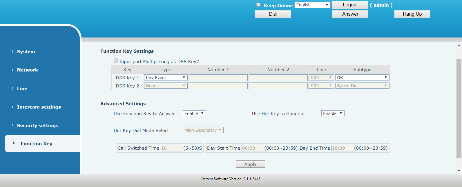
5.6 Function Key
Function Key Settings
DSS Keys can be configured according to the following types: Key Event, Hot Key, Multicast.
Key Event
| Type | Subtype | Usage |
|---|---|---|
| Key Event | None | No response |
| Release | Delete password input, cancel dialing input and end call | |
| OK | Identification key |
Hot Key
Enter the phone number in the input box. When you press the shortcut key, device will dial the preset telephone number. This button can also be used to set the IP address: you can press the shortcut key to directly make an IP call.
| Type | Number | Line | Subtype | Usage |
|---|---|---|---|---|
| Hot Key | Target SIP account or IP address | Corresponding SIP line | Speed Dial | Using Speed Dial mode together with Enable Speed Dial Hangup can define whether this call is allowed to be disconnected when the speed dial key is pressed again. |
| Intercom | If the caller's phone supports the intercom feature, the device can automatically answer intercom calls. |
Multicast
Multicast function is to deliver voice streams to configured multicast address; all equipment monitored the multicast address can receive and play it. Using multicast functionality would make deliver voice one to many which are in the multicast group simply and conveniently.
| Type | Number | Subtype | Usage |
|---|---|---|---|
| Multicast | Enter the host IP address and port number separated by a colon. | G.711A | Narrowband speech coding (4Khz) |
| G.711U | |||
| G.722 | Wideband speech coding (7Khz) | ||
| G.723.1 | Narrowband speech coding (4Khz) | ||
| G.726-32 | |||
| G.729AB |
Operation mechanism
You can define the Function Key configuration with multicast address, port and used codec. The device can configure via WEB to monitor the multicast address and port. When the device make a multicast, all devices monitoring the address can receive the multicast data.
Calling configuration
If the device is in calls, or it is three-way conference, or initiated multicast communication, the device would not be able to launch a new multicast call.
Advanced Settings
| FIELD | DESCRIPTION |
|---|---|
| Input port Multiplexing as DSS Key2 | Enable / disable input port reuse for DSS key 2. |
| Use Function Key to Answer | Enable / disable Function Key to answer |
| Use Hot Key to Hangup | Enable / disable Hot Key to hang up |
| Hot Key Dial Mode Select |
This field is enabled only when DSS Key is defined as a Hot Key. Number 1 Transfer Call Number 2 Mode Select.
User just press the speed dial key once. |
| Call Switched Time |
This field is enabled only when Main-Secondary mode is selected. Set number 1 to transfer call number 2 time, default 16 seconds. |
| Day Start Time |
This field is enabled only when Day-Night mode is selected. Set the start time of the day. |
| Day End Time |
This field is enabled only when Day-Night mode is selected. Set the end time of the day. |