

Infinity 5000 Series - Configuring VLAN
Introduction
About VLAN
VLAN (Virtual Local Area Network) is used to logically divide a physical network into several broadcast domains. VLAN membership can be configured through software instead of physically relocating devices or connections. VLANs address issues such as scalability, security, and network management. Routers in VLAN topologies provide broadcast filtering, security, address summarization, and traffic-flow management. By using VLANs, one can control traffic patterns and react quickly to relocations. VLANs provide the flexibility to adapt to changes in network requirements and allow for simplified administration.
IEEE 802.1Q
IEEE 802.1Q is the networking standard that supports VLANs on an Ethernet network. The specification defines a standard method for tagging Ethernet packets with VLAN membership information. Portions of the network which are VLAN-aware (i.e., IEEE 802.1Q conformant) can include VLAN tags. Traffic on a VLAN-unaware (i.e., IEEE 802.1D conformant) portion of the network will not contain VLAN tags. When a frame enters the VLAN-aware portion of the network, a tag is added to represent the VLAN membership of the frame's port or the port/protocol combination, depending on whether port-based or port-and-protocol-based VLAN classification is being used. Each frame must be distinguishable as being within exactly one VLAN. A frame in the VLAN-aware portion of the network that does not contain a VLAN tag is assumed to be flowing on the native (or default) VLAN.
802.1Q adds a 4-byte tag between the source MAC address and the Ethernet type fields of the Ethernet frame. Two bytes are used for the tag protocol identifier (TPID), the other two bytes for tag control information (TCI). The TCI field is further divided into PCP(Priority Code Point), CFI (Canonical Format Indicator), and VID (VLAN ID).
Voice VLAN
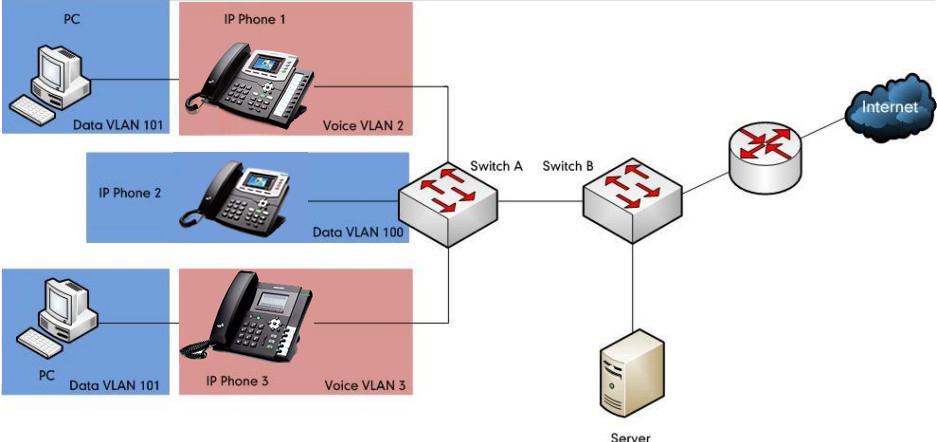
As voice traffic is delay and jitter sensitive for the IP phone, it requires higher priority over data traffic to reduce delay and packet loss during transmission. To simplify configuration procedures and better manage voice transmission policies, the connected switch can be configured to provide voice VLAN function and transmit the voice traffic of the IP phone in a dedicated VLAN, called voice VLAN.
Voice VLAN is a special access port feature of the switch which allows IP phones to be automatically configured and easily associated with a logically separate VLAN. This feature provides various benefits, but one particular benefit is that when voice VLAN is enabled on a switch port, this port is also enabled to allow simultaneous access for a PC.
This feature allows a PC to be daisy chained to an IP phone and the connection for both PC and IP phone to be trunked through the same physical Ethernet cable.The purpose of VLAN configurations on the IP phone is to insert tag with VLAN information to the packets generated by the IP phone. When VLAN is properly configured for the ports (Internet port and PC port) on the IP phone, the IP phone will tag all packets from these ports with the VLAN ID. The switch receives and forwards the tagged packets to the corresponding VLAN according to the VLAN ID in the tags described in IEEE Std 802.3.
Benefits of using VLANs
VLANs offer many benefits that are not found in typical LANs. Major benefits of segregating IP phones into VLAN(s) are listed as below:
- Performance Enhancements: VLAN is used to minimize the broadcast domain. Creating smaller domain for IP phone can reduce overhead and limit resource utilization. Additionally, less traffic will need to be routed, and the latency added by routers will be reduced.
- Ease of Administration: Much of the cost associated with network additions and relocations can be saved through the use of VLANs. IP phone can be shifted from one workgroup or department to another without installing new network cabling and reconfiguring hubs or routers.
- Security: VLANs can be used to create secure user groups and prevent others outside of the broadcast domain from receiving sensitive data of the IP phone. They can also be used to enhance firewall functions and restrict network access for one or more users. By segregating IP phones into VLANs, security filters can be implemented in the network to prevent the IP phones from receiving unnecessary traffic from other devices. This helps prevent disruption due to DoS attacks or attempts to compromise the devices. It also allows locking down access to configuration and servers to only allow access from the IP phones.
VLAN on Infinity phones
There are three ways to get VLAN ID for Internet (WAN) port, but the VLAN used is chosen by priority of each method. The priority is:
- LLDP
- Manual
- DHCP VLAN.
LLDP
LLDP (Link Layer Discovery Protocol) allows Ethernet network devices to receive and/or transmit device-related information to directly connected devices on the network that are also using the protocol, and store the information that is learned about other devices. Information gathered with LLDP is stored in the device as a management information database (MIB) and can be queried with the Simple Network Management Protocol (SNMP) as specified in RFC 2922. LLDP transmits information as packets called LLDP Data Units (LLDPDUs). An LLDPDU consists of a set of Type-Length- Value (TLV) elements, each of which contains a particular type of information about the device or port transmitting it.
Each of the TLV components has the following basic structure:
| Type | Length | Value |
|---|---|---|
| 7 bits | 9 bits | 0 - 510 octets |
LLDP supports advertising the following TLVs:
- Mandatory LLDP TLVs: Chassis ID, Port ID, and Time to Live (TTL) are included in an LLDPDU by default.
- Optional LLDP TLVs: System Name, System Description and so on, the phone sends the optional TLVs along with the mandatory TLVs in an LLDPDU.
- Organizationally Specific TLVs: MAC/PHY Configuration/Status and Port VLAN ID, which are defined in IEEE Standard 802.3 and 802.1 respectively.
The LLDP frame ends with a special TLV, named end of LLDPDU in which both the type and length fields are 0.
LLDP -MED
LLDP -MED (Media Endpoint Discovery) is published by the Telecommunications Industry Association (TIA). It is an extension to LLDP that operates between endpoint devices and network connectivity devices. LLDP -MED specifically provides support for voice over. IP (VoIP) applications and provides the following capabilities:
- Capabilities Discovery—allows LLDP -MED endpoints to determine the capabilities that the connected device supports and has enabled. It can be used to indicate whether the connected device is a phone, a switch, a repeater, etc.
- Voice VLAN Configuration—provides a mechanism for a switch to notify a device which VLAN to use, which enables ―plug and play‖ networking.
- Power Management—provides information related to how the device is powered, power priority, and how much power the device needs.
- Inventory Management—provides a means to manage device and the attributes of the device such as model number, serial number, software revision, etc.
- Location Identification Discovery—provides location information from the switch to the device when making an emergency call.
In addition to the TLVs advertised by LLDP, LLDP -MED also supports advertising the following TLVs:
- LLDP -MED capabilities TLV
- Network policy TLV
- Power management TLV
- Inventory management TLV
- Location identification TLV (not supported by IP phones)
It should be noted that either LLDP or LLDP -MED—but not both—can be used at any given time on an interface between two devices.
LLDP Feature on Infinity phones
LLDP provides exceptional interoperability benefits, IP telephony troubleshooting, automatic deployment of policies and advanced PoE (Power over Ethernet). When LLDP feature is enabled on IP phones, the IP phones periodically advertise their own information to the directly connected LLDP -enabled switch. The IP phones can also receive LLDP packets from the connected switch. When the application type is "voice", IP phones decide whether to update the VLAN configurations obtained from the LLDP packets. When the VLAN configurations on the IP phones are different from the ones sent by the switch, the IP phones perform an update immediately. This allows IP phones to be plugged into any switch, obtain their VLAN IDs, and then start communications with the call control.
TLVs supported by IP phones are summarized in this table:
| TLV Name | TLV Type | Description |
|---|---|---|
| Mandatory TLVs | Chassis ID | Specifies the IP address of the sending port. |
| Port ID | Specifies the MAC address of the IP phone. | |
| Time To Live | Specifies the life of the transmitted information on the IP phone. The default value is 180 seconds. | |
| End of LLDPDU | Marks the end of the TLV sequence in the LLDPDU. No further processing of TLVs after this is necessary. This is a mandatory TLV and therefore must be present at the end of the data stream. | |
| Optional TLVs | System Name | Specifies the administratively-assigned name for the IP phone The default value is "UCxxx". |
| System Description | Specifies the description of the IP phone. The default value is IP Phone. | |
| System Capabilities | Specifies the supported and enabled capabilities of the IP phone. The supported capabilities are Bridge, Router and Telephone. The enabled capabilities are Bridge and Telephone by default. | |
| Port Description | Specifies the description of the sending port. The default value is "WAN PORT". | |
| IEEE Std 802.3 Organizationally Specific TLV | MAC/PHY Configuration/Status |
Specifies duplex and bit rate settings of the IP phone. The Auto Negotiation is supported and enabled by default. The advertised capabilities of PMD Auto-Negotiation are: 100BASE-TX (full duplex mode) 100BASE-TX (half duplex mode) 10BASE- T (full duplex mode) 10BASE- T (half duplex mode) |
| LLDP -MED TLVs | Media Capabilities |
Specifies the MED device type of the IP phone and the supported LLDP -MED TLV type can be encapsulated in LLDPDU. The supported LLDP -MED TLV types are:
|
| Network Policy | Specifies the port VLAN ID, application type, L2 priority and DSCP value. | |
| Extended Power-via-MDI | Specifies power type, source, priority and value. | |
| Inventory – Firmware Revision | Specifies the firmware revision of IP phone. | |
| Inventory – Serial Number | Specifies the serial number of IP phone. | |
| Inventory – Manufacturer Name | Manufacturer name of IP phone. |
Configuring LLDP Feature
LLDP is disabled on IP phones by default. You can configure LLDP via web interface, phone interface or using the configuration file. You can also configure the sending frequency of LLDP packet. The default sending frequency is 120s.
To configure LLDP feature via web interface:
- Navigate to the Network -> Advanced page.
- In the LLDP block, set Active to Enabled.
- Enter the desired time (in seconds) in the Packet Interval (1~3600s) field.
- Click the SaveSet button and the phone will reboot automatically.
To configure LLDP feature via phone interface:
- Press Menu -> Settings -> Advanced Settings (default password is admin) -> Network -> LLDP.
- Press the Switch soft key to select Enable for Active field.
- Enter the desired time (in seconds) in the Packet Interval (1~3600s) field.
- Click the Save soft key and the phone will reboot automatically.
Verifying the Configuration
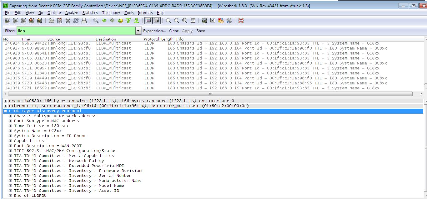
After LLDP feature is enabled, the IP phone performs the following:
- Periodically advertises information (e.g., hardware revision, firmware revision, serial number) of the IP phone to a multicast address on the network.
- Allows LLDP packets to be received from the Internet (WAN) port.
- Supports the MAC/PHY configuration (e.g., speed rate, duplex mode).
- Obtains VLAN info from the network policy , this takes precedence over manual settings.
The following figure shows the LLDP packets sent and received by the IP phone, each packet contains multiple TLVs.
DHCP VLAN
IP phones support VLAN discovery via DHCP. When the VLAN Discovery method is set to DHCP, the IP phone will detect DHCP option for a valid VLAN ID. The predefined option 132 is used to supply the VLAN ID by default. You can customize the DHCP option used to detect the VLAN ID. Besides, you can use the DHCP option 133 to get the 802.1p priority of VLAN. In addition, we also support configure multiple configurations with only one option. Option 43 is a comprehensive configuration item. You can put option 132, option 133 and so on into it. The IP Phone will get the information you configured from option 43. The specific configuration method will be described in detail later.
Configuring DHCP option on a Tftpd32
Before using DHCP VLAN feature on IP phones, you must make sure that the DHCP option on the DHCP server is configured properly. This section provides instructions on how to configure a DHCP option for windows using an application that provides TFTP and DHCP services installed on your computer (e.g. Tftpd32).
To configure DHCP option 132 using Tftpd32:
- Start the Tftpd32 application.
- Select the Current Directory and Server interfaces.
-
Click the DHCP server tab.
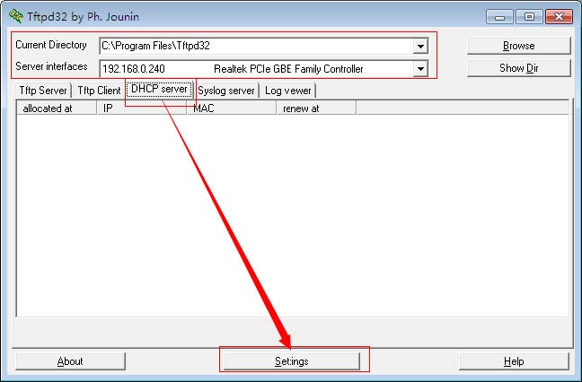
- Click the Settings button.
-
Select the DHCP Server.
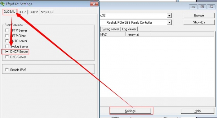
-
Select the DHCP tab and configure the options.
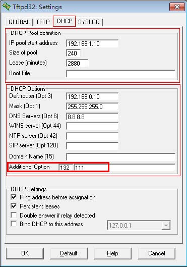
- Click the OK button.

Configuring DHCP VLAN on Infinity phone
DHCP VLAN is disabled on IP phones by default. The DHCP option is 132.
To configure DHCP VLAN feature via web interface:
- Navigate to the Network -> Advanced page.
- In the DHCP VLAN section, set Active to Enable.
- Click the SaveSet button.
- Click OK to reboot the phone.
To configure DHCP VLAN feature via phone interface:
- Press Menu -> Settings -> Advanced Settings (default password is admin) -> Network -> DHCP Vlan.
- Press the Switch soft key to set DHCP Vlan field to Enable.
- Press the Save soft key and then reboot the phone manually.
Verifying the Configuration
When the IP phone is configured to use DHCP for VLAN discovery, and the DHCP option is set to 132, the following processes occur:
- The IP phone broadcasts a DHCP Discover message to find out if there is a DHCP server available.
- If the DHCP server sends a DHCP Offer message with the Option 132, the phone will accept the Offer, send a DHCP Request, and save the VLAN ID provided by the DHCP server in the DHCP option 132.
- After the DHCP server has sent the ACK message to the phone, the phone will release the leased IP address and start a new DHCP Discover cycle using the now known Voice VLAN ID tag. After this process, the phone will send all packets with the VLAN ID learned from the DHCP server in the DHCP option 132.
The following figure shows the DHCP messages sent and received by the IP phone:

Configuring DHCP option 133
You can configure this option the same way as option 132, this option contains the WAN Port priority. When you configure this option on the server, and change the state of DHCP Vlan to enable, you can see the priority you set in the web interface.
Configuring DHCP option 43
You can configure this option the same way as option 132. This option mainly introduces the data format. Because this option can contain multiple configurations, some special formatting is required when configuring the data to distinguish between the various configurations.
Suppose you want to configure the option 132 and option 133 together, the data format for each option is as follow:
OPTION ID + ( Length of configuration (Bit) +1 ) + configuration + 00
To configure the option 132 as 31, the data is:
132 + 3 + 31 + 00
where
- 132: OPTION ID
- 3: the length of 31 is 2 bit, plus the length of 00 (separator), the result is 3.
- 31: the configuration
- 00: separator between configurations.
The data type of option 43 is hexadecimal, so we need to make some changes to the above data.
| Original | Hexadecimal |
|---|---|
| 132 (integer) | 84 |
| 3 (integer) | 03 |
| 31 (string) | 3331 |
| 00 (hexadecimal) | 00 |
The data to configure option 132 as 31 will look like this:
84 03 33 31 00
Using the same method as above, we now calculate the data to configure option 133 as 5.
Start off with the data value:
133 + 2 + 5 + 00
Next, change the data to hexadecimal
85 02 35 00
The data for option 132 and option 133 can now be put together as:
84 03 33 31 00 85 02 35 00
Now the option 43 contains information for both option 132 and 133. when the IP phone gets the data for option 43, it knows the option 132 is 31 and option 133 is 5.
Priority and support of OPTION 43
Except for options 132 and 133 above, option 43 also supports option 66, 67 128 and 150.
Option 43 has the highest priority. If you have configured both options 43 (contains option 132,133,66,67,128,150) and 132,133,66,67,128,150 at the same time. The configuration will be based on option 43.
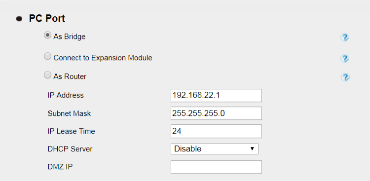
VLAN under Bridge Mode
When using Bridge Mode, PC Port VID is supported. When your PC is connected to LAN Port, data (from your PC to switch) will be tagged with " PC Port VID ".
Network -> PC Port page
Network -> Advanced page
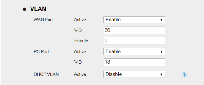
With the above configuration, VOIP (SIP RTP) packets sent from the device will be tagged with VLAN ID 66, data packets sent from your PC to switch will be tagged with VLAN ID 18.
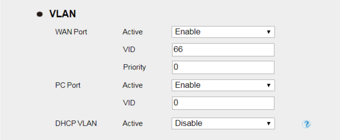
Or with the above configuration, VOIP (SIP RTP) packets sent from the device will be tagged with VLAN ID 66, while data packets sent from your PC to switch will be tagged with UNTAG VLAN ID.
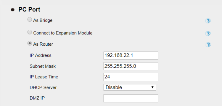
VLAN under NAT Mode
When using NAT mode, VLAN ID is port based, you cannot set Data VLAN ID. If the VLAN ID arranged for the device is 66, then the VLAD ID must be set to the same value.
Network -> PC Port page
Network -> Advanced page
In this case, all ethernet packets sent out from the device will be tagged with VLAN ID 66.