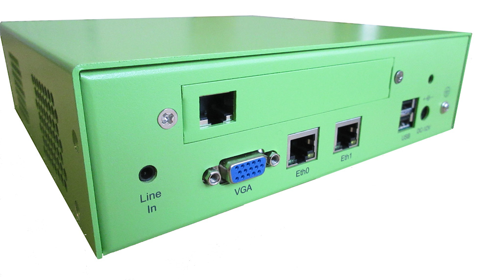
Install PRI-1S card in the Galaxy 250
Prerequisites
Tools
-
#2 Philips screwdriver
- Slotted screwdriver
Accessories
The following accessories are shipped with the PRI-1S card. if you are re-using an existing card and do not have the following accessories, please contact E-MetroTel to order the PRI-1S installation kit.
-
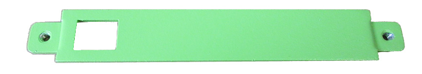
Single-port cover plate

-
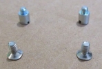
Metal risers and screws
-
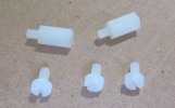
White plastic risers and screws


Step One: Opening Galaxy 250 chassis and replacing cover plate
Power down the Galaxy 250 and unplug all cables from the box.
Remove the chasis cover from the Galaxy 250 by removing all 8 screws, 4 on each side of the chasis.
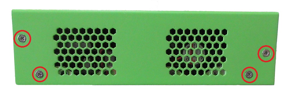
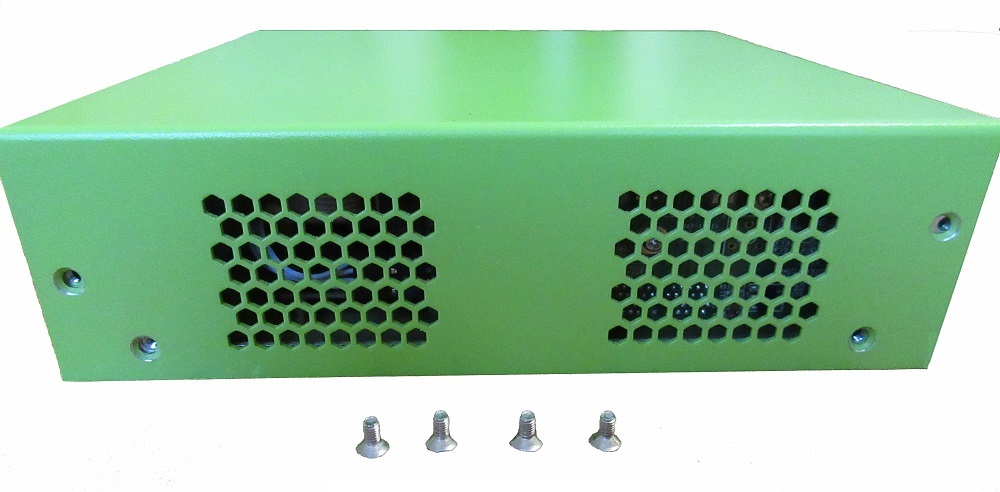
After all 8 screws have been removed, lift the cover up.

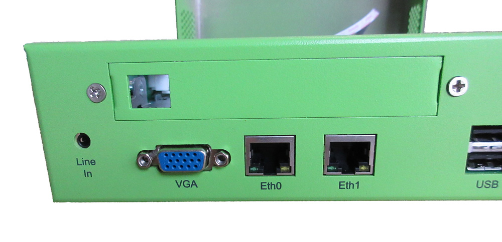
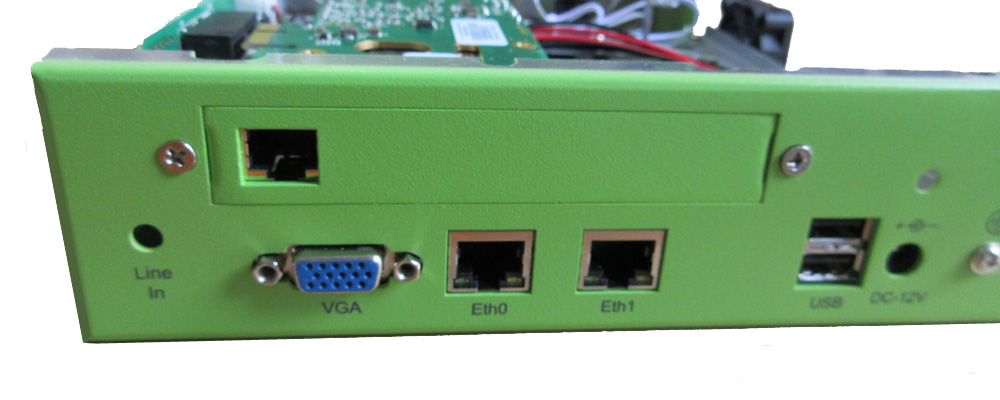
On the back of the Galaxy 250, remove the 2 screws holding the cover plate, then remove the cover plate.

Replace the cover plate with the single-port cover plate.
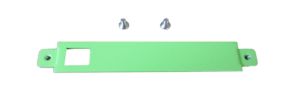
Insert the single-port cover plate and secure with the two flathead screws.
Step Two: Preparing the Motherboard
Disengage the side board
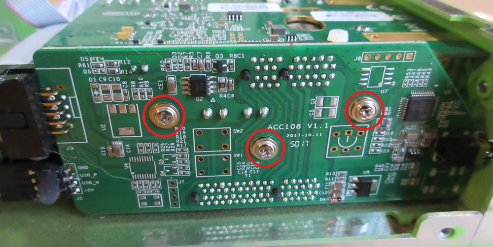
Remove the 3 screws holding the board located on the side of the motherboard.
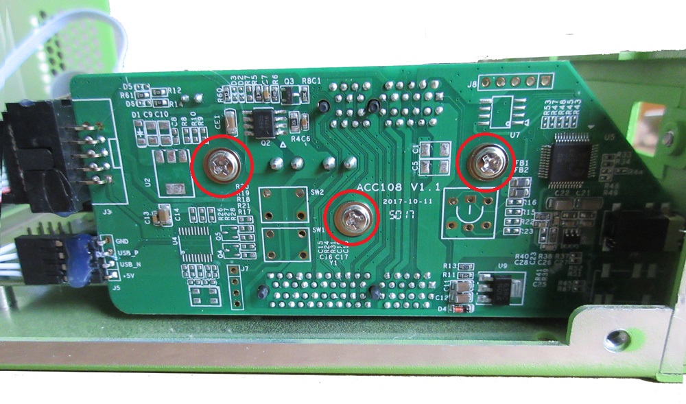
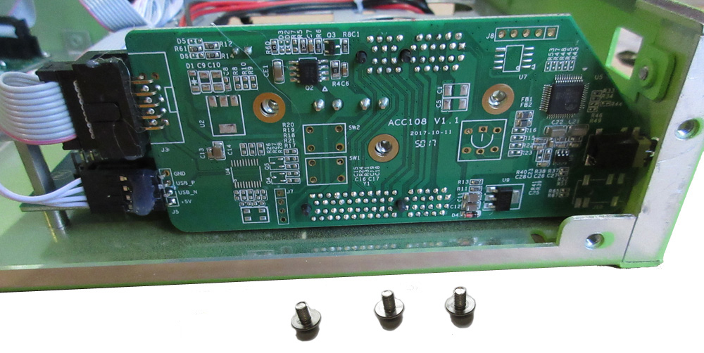
Use a screwdriver as a lever, gently pry the side board away from the motherboard.
(You just need some space between the side board and the motherboard, no need to completely remove the side board.)

Move bracket to different location on the motherboard
Locate the bracket at the corner of the motherboard.
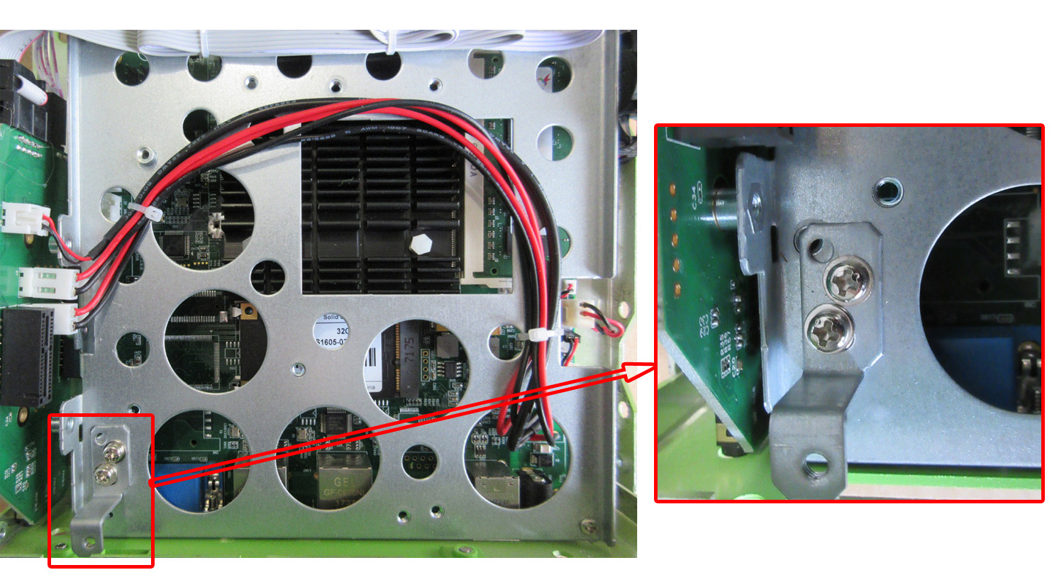
Loosen the 2 screws and relocate the bracket to the opposite corner of the motherboard. Secure the bracket onto the motherboard with a single screw, insert the 2nd screw in a nearby slot.

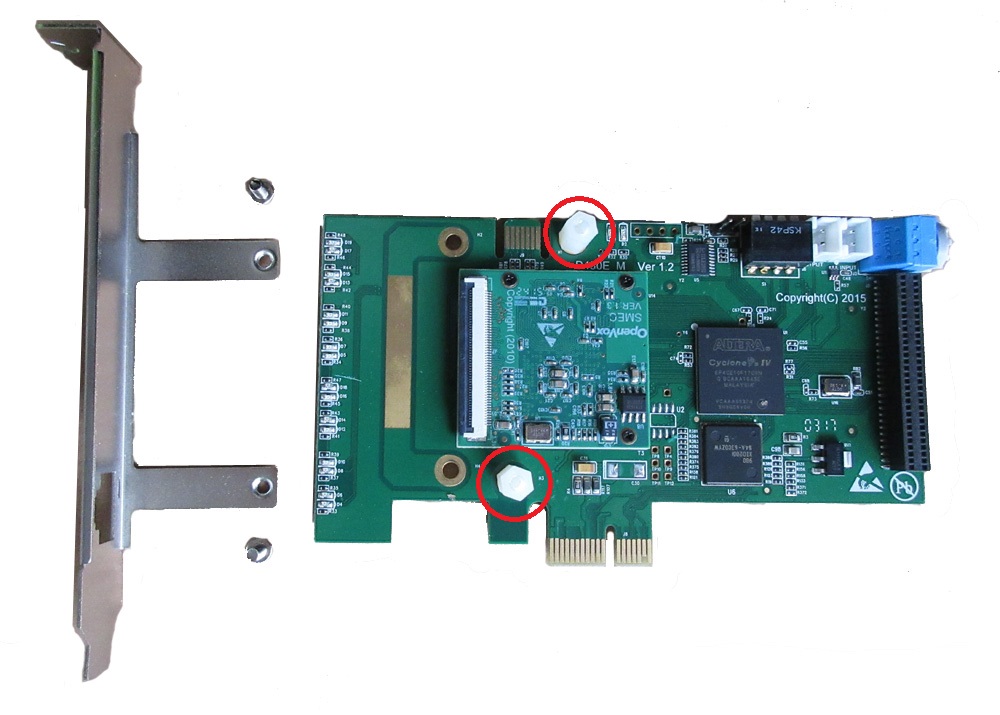
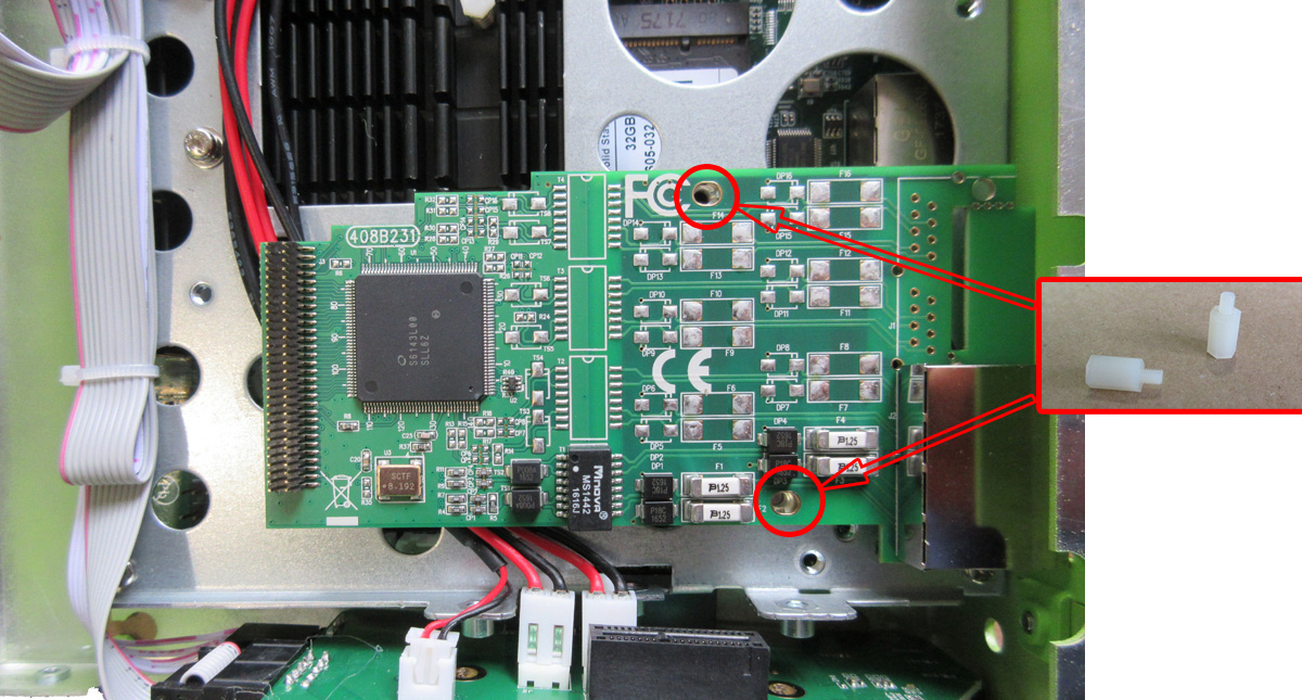
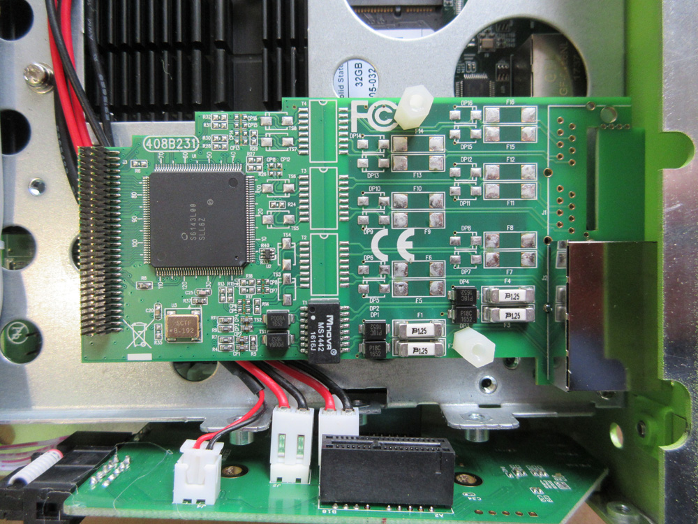
Insert risers on the motherboard
Have ready the following metal risers and plastic screw.
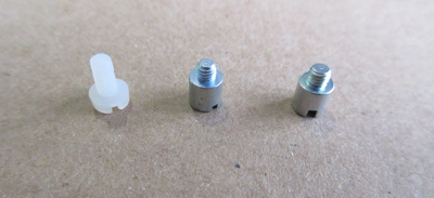
Insert them onto the motherboard at the locations as shown below. Tighten them with the appropriate screwdrivers.

Step Three: Preparing the PRI-1S card
Remove the white plastic screw holding the top and bottom cards together.

Gently separate the top and bottom cards. Loosen the 2 silver screws holding the bracket.
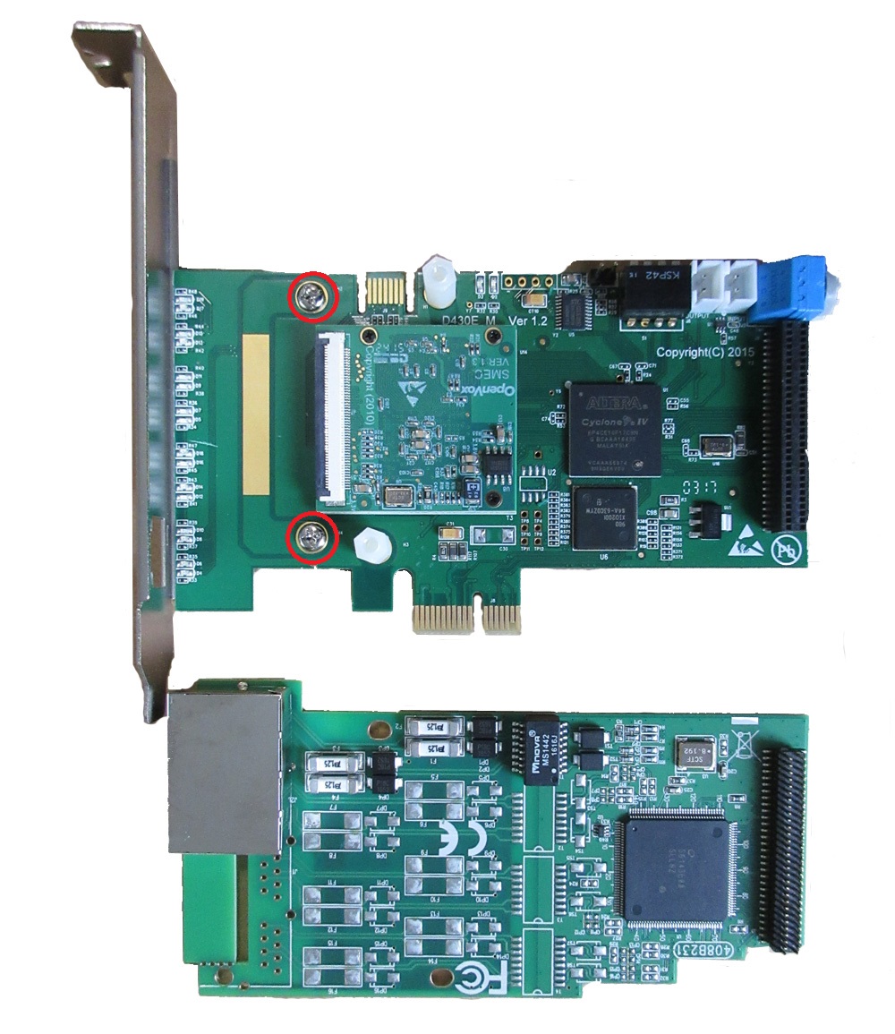
Remove the bracket and remove the remaining white plastic risers and screws.

Step Four: Install the PRI-1S card onto the motherboard
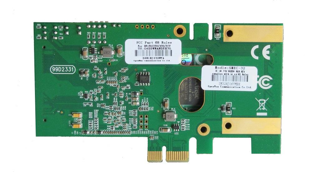
Take the PRI-1S bottom card (the one with the network connector port) and place it onto the motherboard.
 Bottom card |
 Top card |
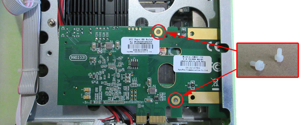
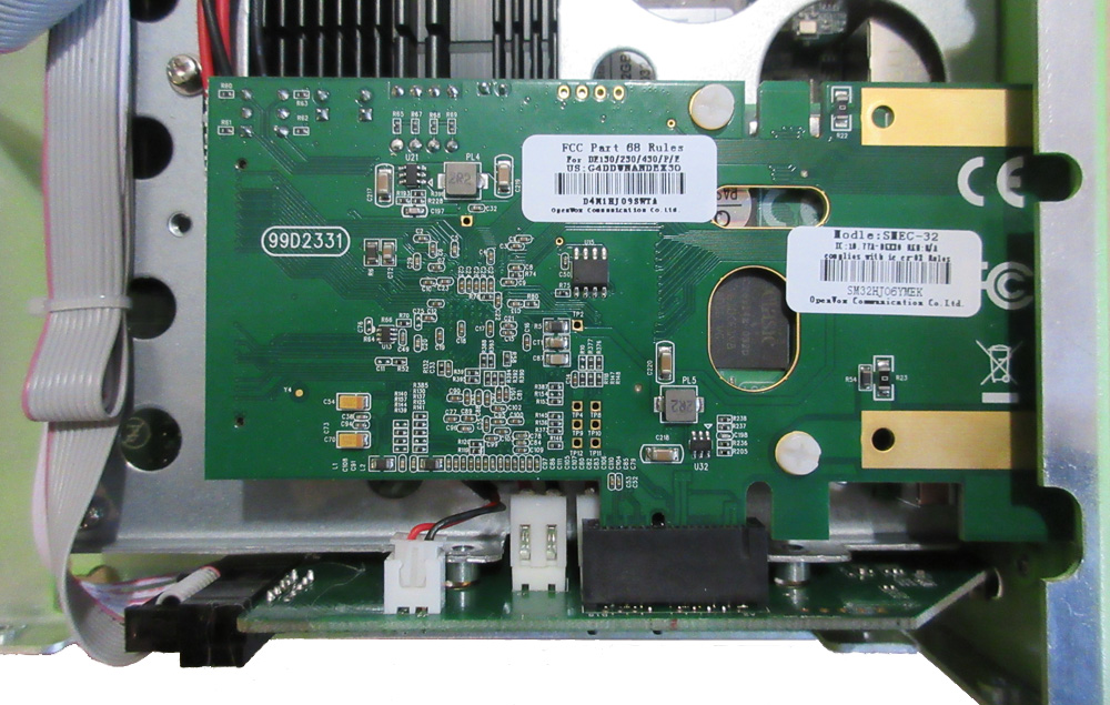
Align the holes on the card with the risers on the motherboard and align the network connector with the cover plate hole.

Screw the white plastic risers into the holes and tighten.
Place the PRI-1S top card onto the bottom card. Align the connector pins and press down.
Secure the top card to the bottom card by screwing the 2 white plastic screws into the holes.
Align the gold contacts of the PRI card with the side board, press the side board firmly onto connectors located on the motherboard and the PRI card.

Secure the side board onto the motherboard using the same 3 screws previously removed.
Step Five: Close the Galaxy
Replace the cover and secure the cover with the previously removed 8 screws, 4 screws on each side.
Power up the Galaxy server and the new PRI card will be automatically detected by the system. Proceed to the PSTN Cards page to configure the card.