

Galaxy Expand - Module Installation
Required and Optional Cards
The list of plug-in cards that are either mandatory or optional are described in Galaxy Expand - Platform Overview and Hardware. All cards are inserted in the same manner into the Galaxy Expand chassis, although some cards are restricted to certain slots; those restrictions are noted in their descriptions in the referenced section. In most cases, the slots are physically incompatible with inappropriate cards and prevent the card from being fully inserted. However, even if a card is installed incorrrectly, it is safe and should not cause damage.
All cards use the same process for installing and removing them, with the exception noted below that requires the power to be disconnected before changing the SFS or power supplies,
Card Insertion
Each slot is labeled on the chassis. With the exception of Slot 2b, Slot 7b, and Slot 11b, each of the slots has a both an upper and lower guide rail for ensuring proper alignment of the card prior to inserting. The slots can be seen below:
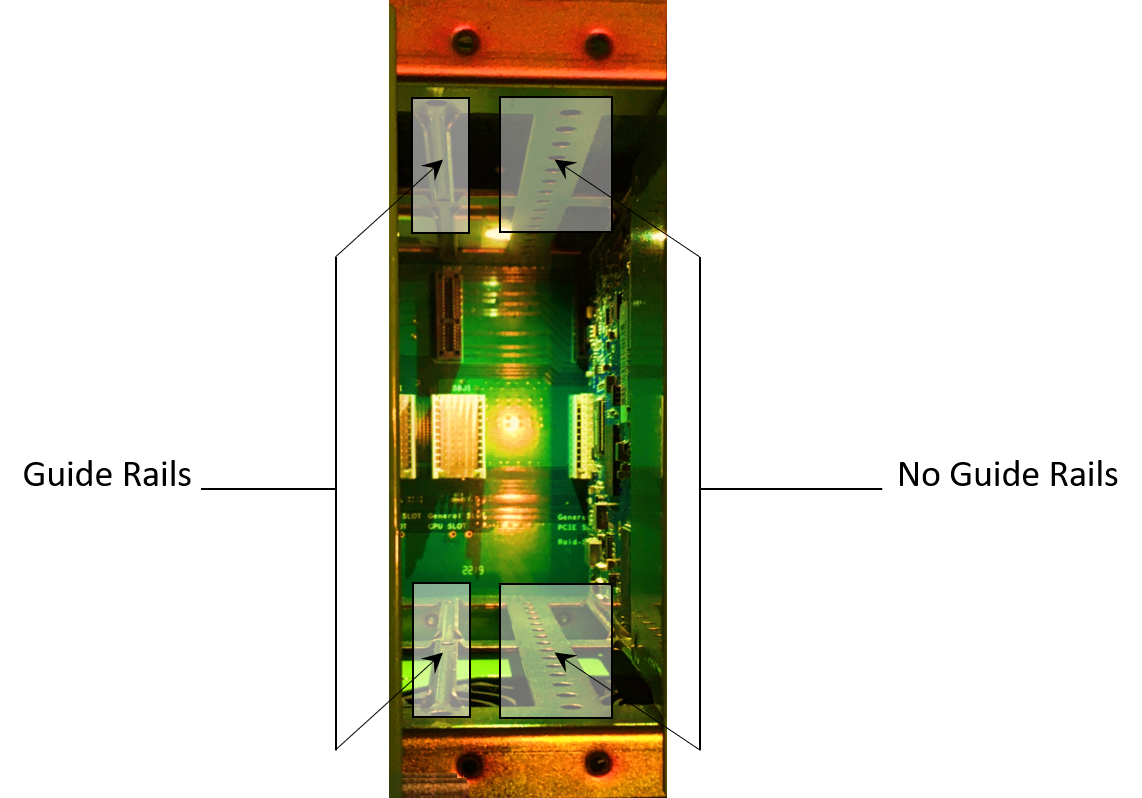
When installing the card, make sure the side of the circuit board with most of the components is facing right, and guide the upper and lower edge of the card into the upper and lower guide rails. Holding the latching screws, slide the card all the way and gently rock the card to seat it in the rear connector. Tighten the latching screws to the chassis to ensure a solid fit.
Unused Card Slots
Ensure that any used card slots have the blank metal plate (baffle) installed to reduce risk of unwanted materials being inserted or dropped into the chassis. Secure the baffles with screws at the top and the bottom rail.
Power Supply Module Insertion
Power Supplies are installed in a similar manner as regular cards. However, they are secured by four screws at each of the corners of the front face plate. Hold the module with the front handles and slide the module in. Once the module has been inserted and secured with the screws, plug in the power supply cord to the module and then to the power source.
Fan Tray Insertion
The Fan Tray is also installed in a similar manner. However, it is secured by two screws on the bottom corners of the front face plate. Hold the tray with the front handles and slide the tray in. Once the tray has been inserted, secure it with two screws.
Cabling
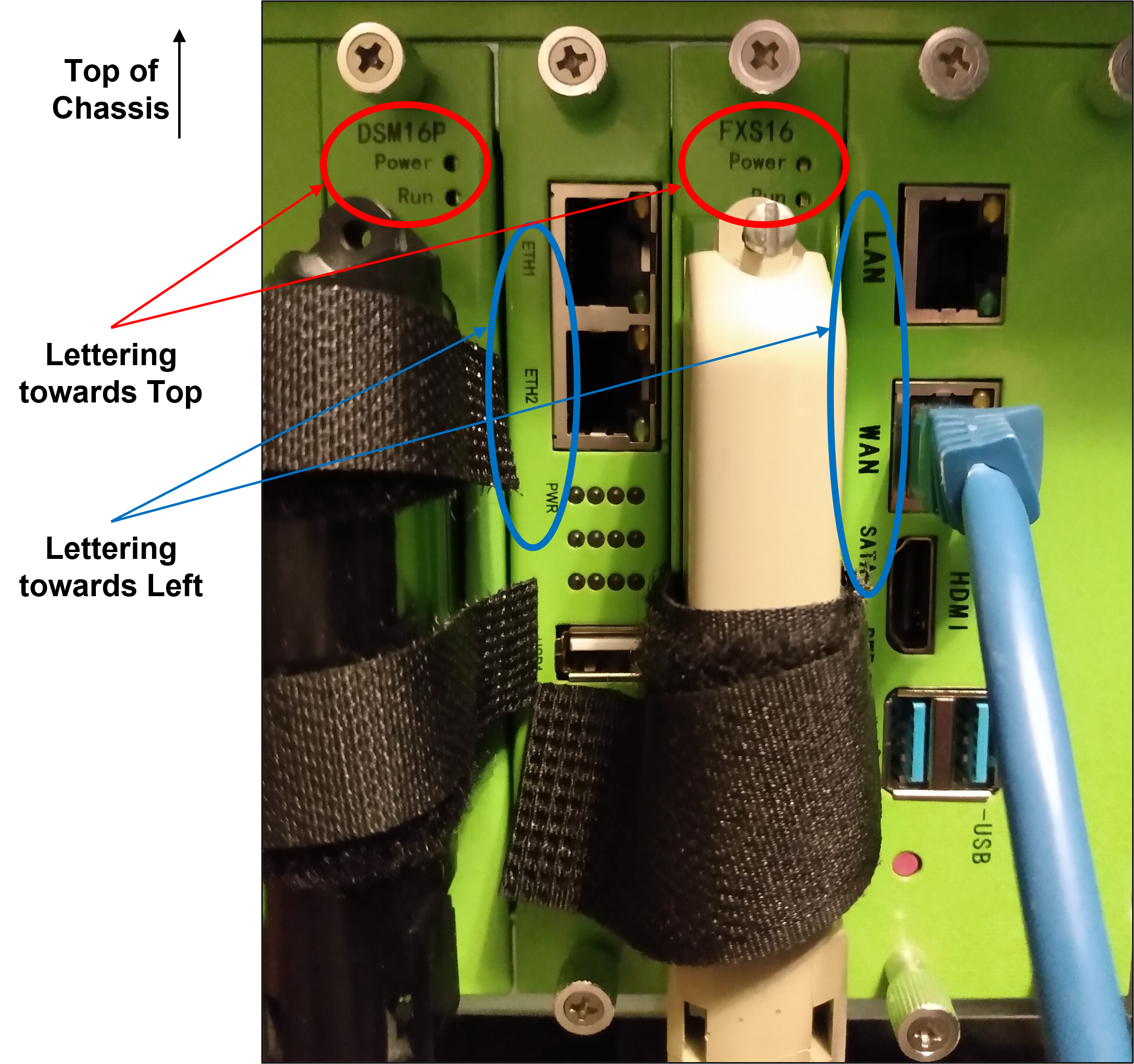
Most 25 Pair Amphenol Telco cable connectors are constructed with a 90 degree bend that results in the cable extending downward from any DSM16p or FXS16 modules in the Galaxy chassis. Therefore, it is recommended that rack or table mounting plans take this cable direction into account and other cables are run accordingly.
The power cables supplied for the each of the Power Supply modules likewise have a 90 degree "downward" bend to ensure that they do not protrude directly from the chassis and risk being inadvertently knocked out of position by someone working or walking nearby.
When connecting a second shelf for expansion, a short, one-foot long ethernet cable can be used to connect the two Switch Fabric cards together to extend the backplane IP network from the main to the expansion unit.