

You are here
Documentation
- InfinityOne Omnichannel (Beta)
- InfinityOne
- Infinity Video Server (Beta)
- InfinityOne Work at Home
- Galaxy Mini
- Galaxy Mini - Table of Contents
- Galaxy Mini - Overview
- Galaxy Mini - Server Hardware
- Galaxy Mini - Supported Phones and Devices
- Galaxy Mini - Front and Rear Panel Interfaces
- Galaxy Mini - FXO/FXS Module Installation
- Galaxy Mini - Connecting the Server to the Network
- Galaxy Mini - Activating and Licensing
- Galaxy Expand
- Galaxy Expand - Table of Contents
- Galaxy Expand - Platform and Hardware Overview
- Galaxy Expand - Module Installation
- Galaxy Expand - Initial Configuration
- Galaxy Expand - Reference Architecture
- Galaxy Expand - Common Configuration
- Galaxy Expand - Standalone UCX Server Configuration
- Galaxy Expand - High Availability UCX Configuration
- Galaxy Expand - Local Gateway (Expansion Chassis) Configuration
- Galaxy Expand - Remote Gateway Configuration
- Galaxy Expand - Survivable Remote Gateway Configuration
- Galaxy Express
- Galaxy Modular Hardware
- Galaxy Analog Cards
- Getting Started with Galaxy Analog Cards
- Galaxy Analog Gateways - IAD Firmware
- Galaxy Analog Cards - Original Firmware
- Galaxy PRI-1 Card
- Galaxy Analog Cards
- Servers and Gateways
- Introduction
- Planning
- Quick Start
- UCX Virtual Machine
- UCX Server
- UCX Web-based Configuration Utility
- System
- Fax
- PBX
- Reports
- Accessories
- My Extension
- Security
- Support
- Survivable Remote Gateway (SRG)
- High Availability (HARC)
- UCX Digital Station Module (DSM16)
- UCX M1/CS1000 Media Gateway
- Digital Gateway
- External Gateways and Devices
- SIP PSTN Trunks
- SIP Trunks
- How-To Guides
- UCX Applications
- UCX Features
- Answer DN Behavior
- Background Music
- Busy Lamp Field (BLF)
- Global BLF key label change
- Parking Lot Monitoring Solutions
- Call Transfer and Recall
- Call Monitoring
- Call Recording Options
- Dial System Fax
- Dictation Service
- Distinctive ring tones
- Fax to Email
- Group Pickup
- Hotline UCX Configuration
- Hotdesking
- Language prompts
- Long Tones
- Ring Again (Call back)
- Shared Call Appearances
- Set Based Configuration
- UCX MADN Emulation Solutions
- Unified Messaging for M1/CS1000 Users
- User Portal
- Voicemail and VmX Locater
- Voicemail Escalation
- Voicemail Message Indicator
- ZapBarge
- Telephones
- Installation Guides
- Product Specifications
- General Information
- Product Bulletins
- Product Notices
- InfinityOne Package Update Required
- UCX 6.0 End-of-Support
- UCX 7.0 and InfinityOne 4.0 General Availability
- VPN Security Update Required
- Email Relay Using Gmail Account Fails Due to Bad Credentials
- InfinityOne Release 2.x End-of-Life
- InfinityOne Android App General Availabililty
- E-MetroTel not affected by Log4j vulnerability
- Web-based GUI Security Enhancements
- User Portal Security Update
- Simplified UCX Configuration for Remote InfinityOne Softphones
- InfinityOne Release 3.0 Server General Availability
- Availability of Connection Sharing
- Availability of Automated Cleanup
- Availability of IP Block List Feature
- InfinityOne Release 2.0 Availability
- Digital Station Module (DSM16) Availability
- UCX Software Updates
- Quotations and Ordering
- Nortel Legacy
- Support and Troubleshooting
- Partner Onboarding
- E-MetroTel Business Practices
- Recurring Services Payment Policy
- Product Licensing
- Extension Provisioning Services
- Subscription Services
- E-MetroTel SIP Trunk E911 Registration
- Reseller Responsibilities
- Software Subscription and Warranty Transfer Request
- Return Material Authorization (RMA) Policy
- Acceptable Use Policy
- E-MetroTel Beta Trial Policy
- E-MetroTel Training Expectations
- 9-1-1 Services Agreement (Canada)
- References
Galaxy Express - Module Installation
Required and Optional Cards
The list of plug-in cards are described in Galaxy Express - Platform and Hardware Overview. All cards are inserted in the same manner into the Galaxy Express chassis
Regardless of which slots a card to which a card is restricted, the same process is used for installed and removing them.
Card Insertion
Each slot is labeled on the chassis (1 and 2). Each of the slots has a both an front and rear guide rail on each side for ensuring proper alignment of the card prior to inserting. The slots and rails can be seen below:
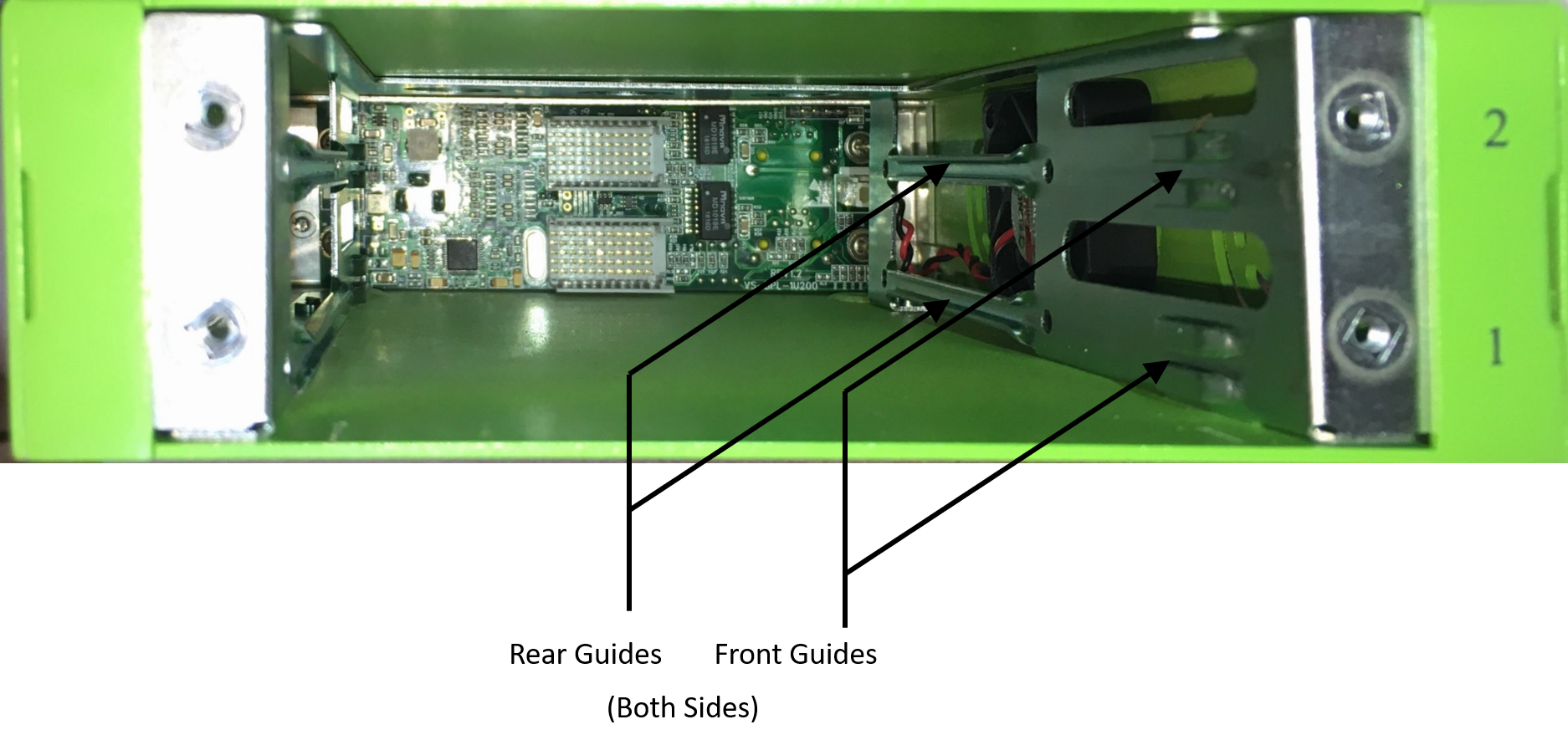
When installing the card, make sure the side of the circuit board with most of the components is facing upward, and guide the upper and lower edge of the card into the upper and lower guide rails. Holding the latching screws, slide the card all the way and gently rock the card to seat it in the rear connector. Tighten the latching screws to the chassis to ensure a solid fit.
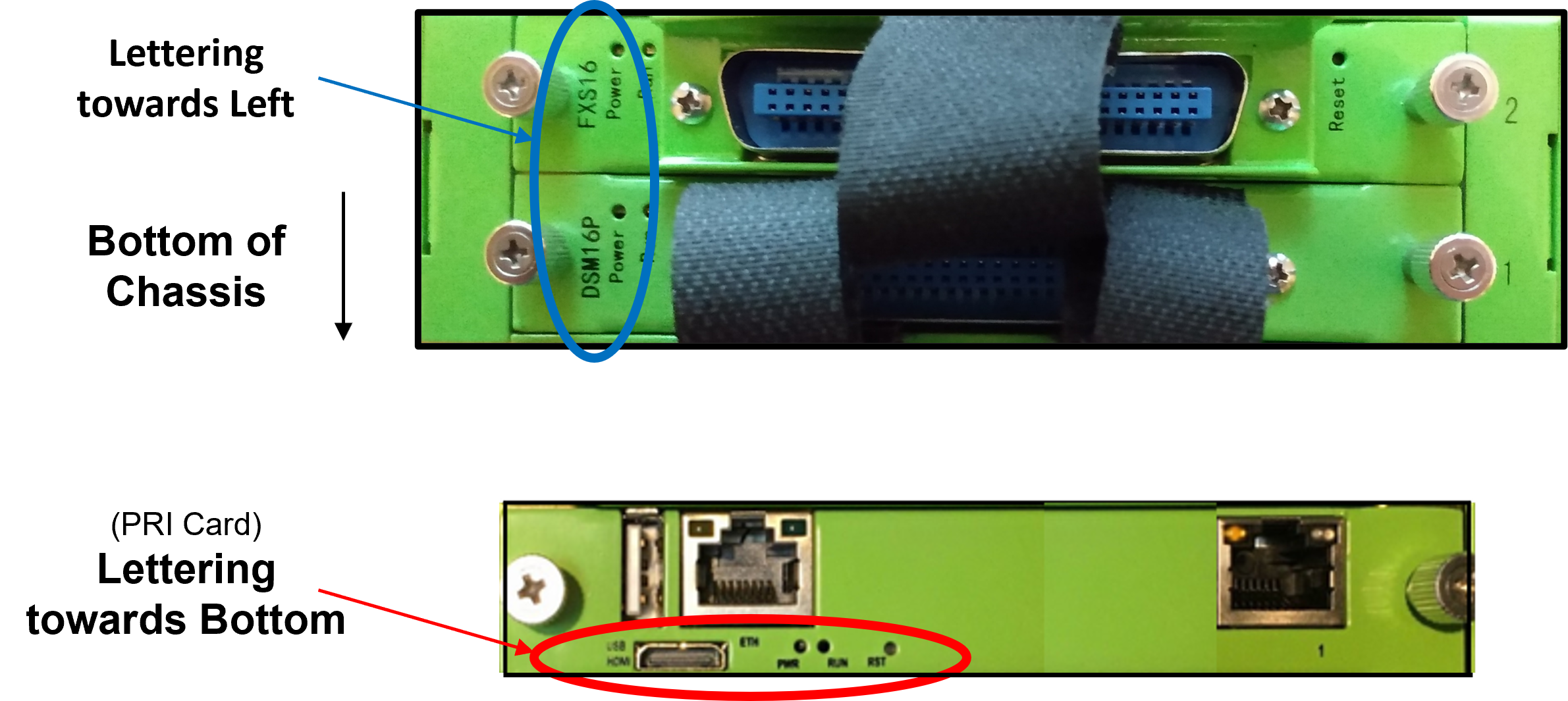
It is possible to install the card upside down if the card is not properly inserted into the guide rails, which could damage the card. Before seating the card into the connector, verify that 1) the card is sliding within the guide rails and that the text is either oriented toward the left-hand side or toward the bottom of the chassis!
Disconnect the power cords prior to inserting or removing any cards.
Once you have installed the cards in the Galaxy Express chassis, you can follow the same steps for initial configuration as for the Galaxy Expand as described in Galaxy Expand - Initial Configuration.
Page Tags:
Galaxy
Express