

Galaxy Mini - FXO/FXS Module Installation
Step One: Preparing the Galaxy Mini for card installation
Power down the Galaxy Mini and unplug all cables from the box.
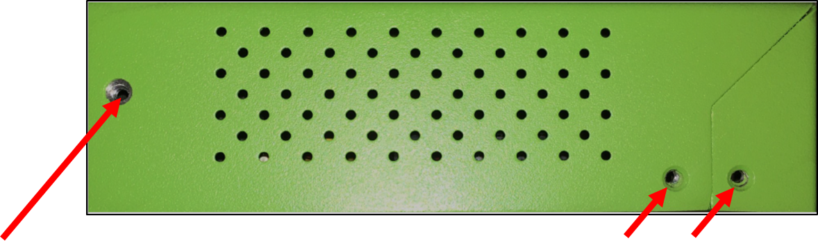
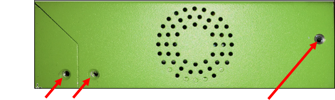
Remove the top cover from the Galaxy Mini by removing 3 screws on each of the sides of the chassis.
Left Side
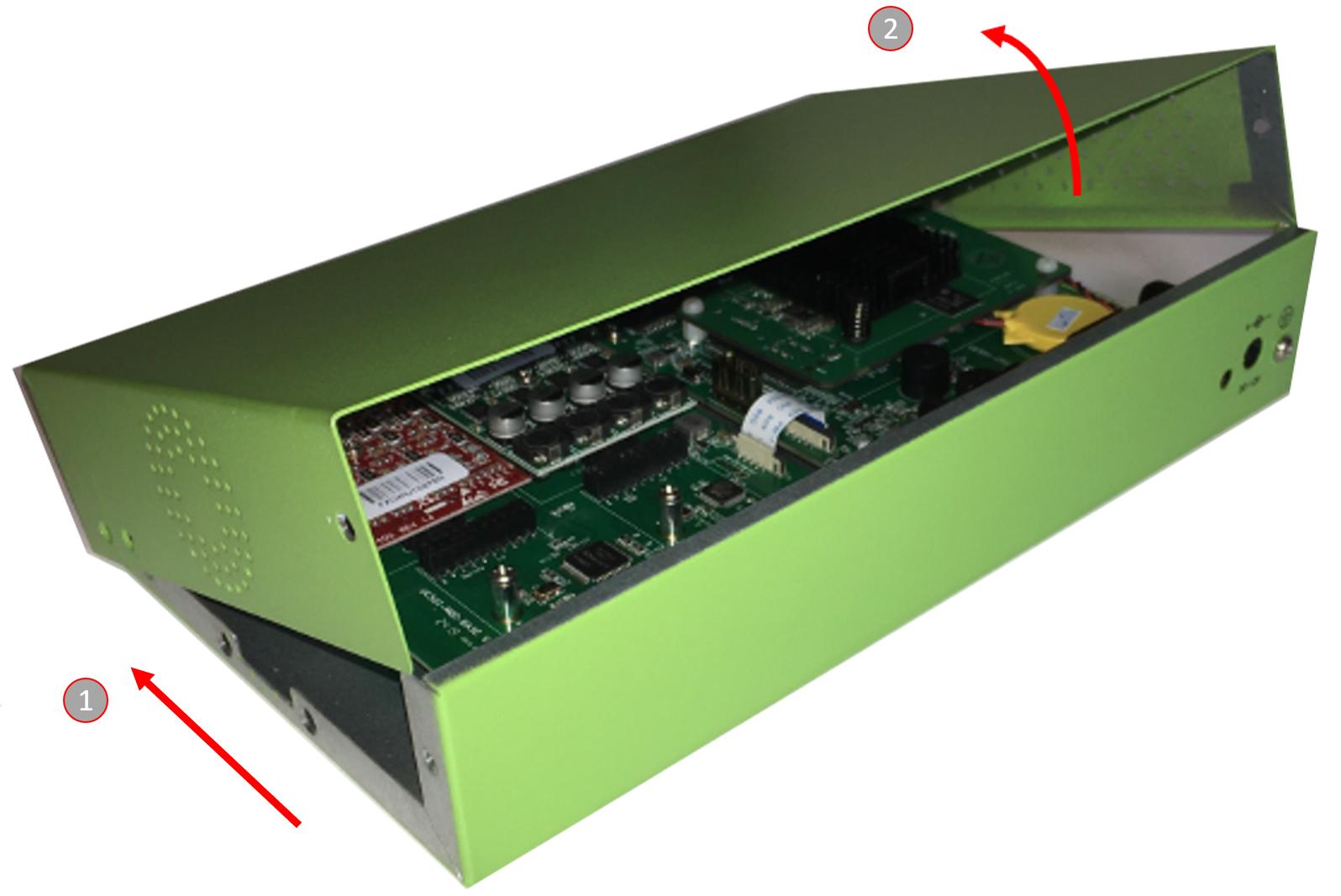
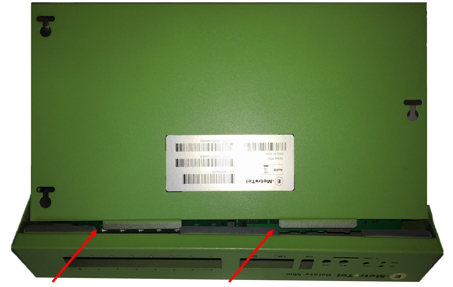
Remove the chassis cover by first sliding the cover back slightly to ensure that the cover will not be impeded by any of the front panel jacks, and then lifting the back edge of the Galaxy Mini up and out of position.
The chassis houses two separate circuit boards, The board on the right is where the FXO / FXS Modules will be inserted.
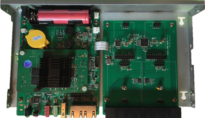
Note that there are four distinct locations for the FXO and/or FXS modules, with the positions identified as per below:
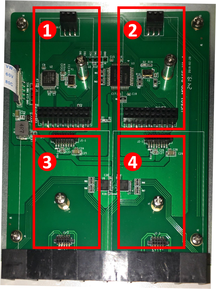
Note that a maximum of two modules can be installed at one time on a Galaxy Mini.
Any combination of 1 Port FXO and/or 1 Port FXS modules can be installed in either Position 1 and Position 2. The system will automatically detect the type of module inserted through the DAHDI interface.
Likewise, any combination of 4 Port FXO and/or 4 Port FXS modules can be installed Position 3 and Position 4 can be configured with either and the system will auto-detect the type.
The system can also support a mixture of one 1 Port module (either FXO or FXS) and one 4 Port module (either FXO or FXS). The system will auto-detect which type of modules are installed and which position they are installed in, but when a 1 Port module is installed in Position 1, the 4 Port module must be installed in Position 4, and if the 1 Port module is installed in Position 2 then the 4 Port module must be installed in Position 3.
Step Two: Installing the FXO or FXS module(s)
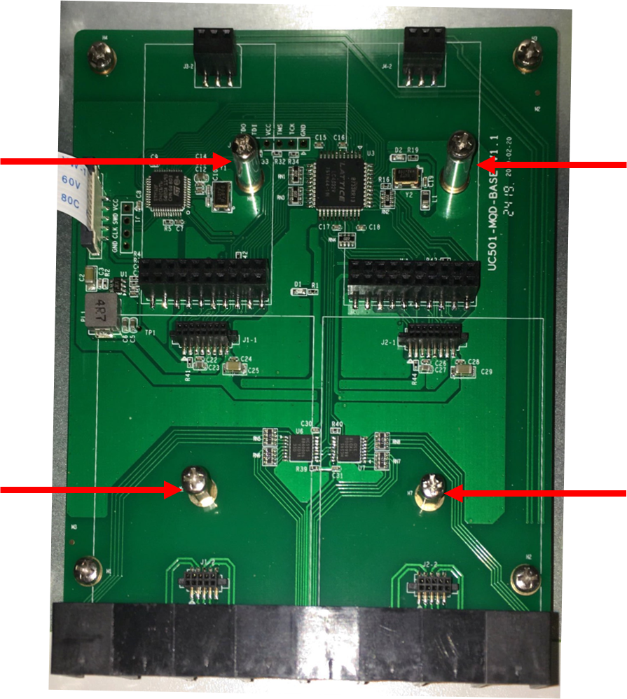
Once you have decided which modules are to be installed and in which module positions, you must remove the screws from the module mounting post(s) that are to be used. These screws are located as follows:
If you are replacing a module that is already installed in one of these positions, both the screw and the existing module removed (see Removing a FXO/FXS module, below).
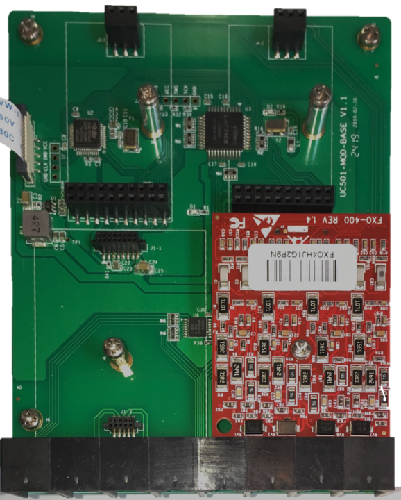
Line the module up (connector-side down, barcode label up) with the connectors and the mounting post associated with the position you will be installing the module. Once you have aligned the module, gently apply pressure on each edge of the module until the module is firmly seated in the connectors. Once seated, re-insert the screw into the mounting post. The following shows a 4 Port FXO card installed in Position 4:
Step Three: Closing the chassis
After completing the installation of each of the up to two modules, place the cover of the chassis upside down on a surface. Position the bottom of the chassis (with the circuit boards) over the cover so that the locking mechanism aligns on each piece:
Gently lower the base of the chassis to until the screw holes on either edge of the base and cover align. Install the screws (3 on each side).
Power up the UCx server and the new Interface Card will be automatically detected by the system. These cards connect to the UCX software as Dahdi-based devices. To configure Analog Extensions, refer to Adding a DAHDI Extension. For Analog Trunks, refer to Adding DAHDI Trunks.
Removing a FXO/FXS module
If you are required for any reason to remove an existing FXO or FXS module, open the chassis per the instructions above.
Once it is open, removing the retaining screw for the module you need to remove.
Using only your fingers, gently rock the module to ease the card from its sockets.
Replace the screw and close the cover per the instructions above.